Introduction to U-Shaped Photoelectric Sensors
U-shaped photoelectric sensors, also known as through-beam sensors, are fundamental components in industrial automation for object detection, counting, and positioning. Their design features a separate emitter and receiver housed in a single U-shaped body, creating a consistent light beam across the gap. The quick-connect wiring system has revolutionized their installation, significantly reducing downtime and wiring errors compared to traditional screw-terminal methods. This guide details the correct procedures and best practices for wiring these sensors using quick-connect (often spring-cage or push-in) technology, ensuring optimal performance and system reliability in demanding environments.
Understanding Quick-Connect Terminal Blocks
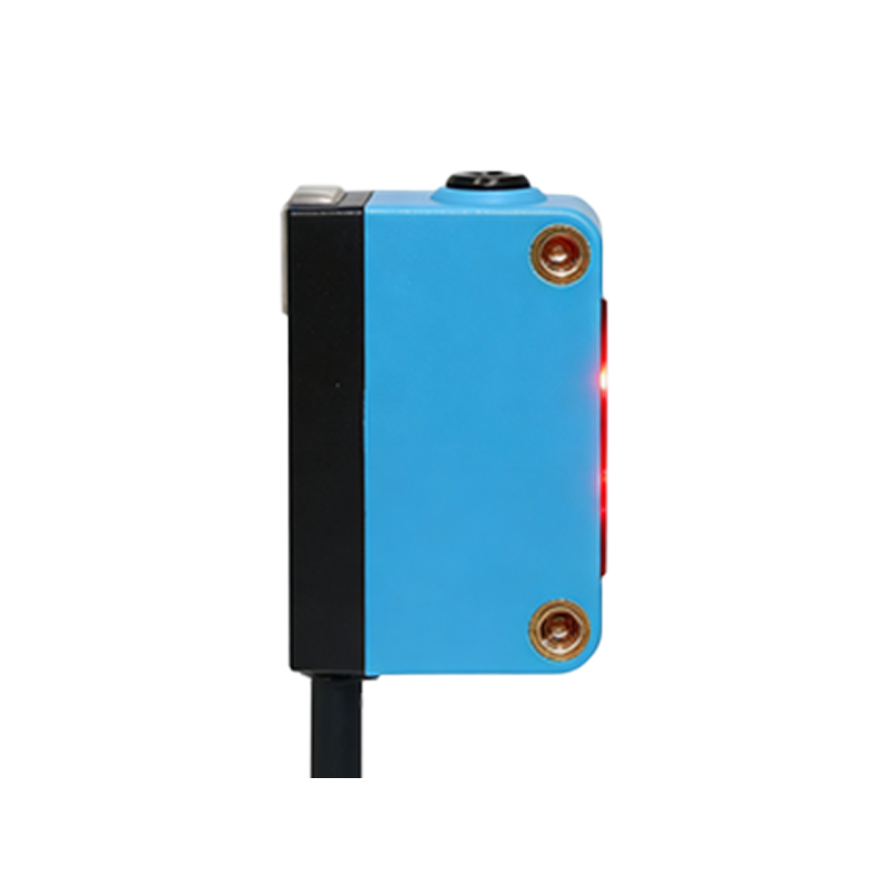
The core of fast installation lies in the quick-connect terminal block. Typically, these sensors have three or four wires: brown (V+ or L+), blue (V- or L-), black (output signal), and sometimes white (complementary output or control line). The terminal block uses a spring-loaded cage mechanism. To insert a solid or finely stranded wire, a user simply inserts a standard screwdriver into the designated release slot, which opens the spring clamp. The prepared wire is then inserted into the now-open terminal hole. Removing the screwdriver allows the spring to clamp down securely on the conductor, creating a gas-tight, vibration-resistant connection. This eliminates the need to twist wires around screws and ensures consistent contact pressure.
Step-by-Step Wiring Procedure
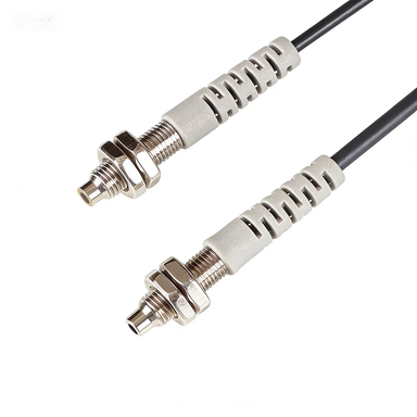
First, ensure the power supply to the control circuit is completely disconnected and locked out. Prepare the connecting cables by stripping approximately 7-10mm of insulation using a proper wire stripper. For best results with stranded wire, a ferrule crimped onto the end is highly recommended to prevent strand fraying and ensure a perfect cylindrical shape for the clamp. Identify the sensor's wiring diagram, usually printed on the side of the housing or in the datasheet. Insert the tool into the release slot above the corresponding terminal. Insert the prepared brown wire into the positive terminal (often marked +V, L+, or 1), the blue wire into the negative/common terminal (marked 0V, L-, or 2), and the black output wire into the switching output terminal (marked OUT, Q, or 3). Gently tug on each wire to confirm a secure mechanical connection.
Electrical Considerations and Power Supply
Always verify the sensor's operating voltage range (e.g., 10-30V DC) and match it with a stable, regulated DC power supply. Incorrect voltage can lead to permanent damage or erratic operation. For DC 3-wire sensors, the load (e.g., a PLC input, relay, or indicator) is connected between the black output wire and the positive or negative rail, depending on whether the sensor provides a PNP (sourcing) or NPN (sinking) output. This configuration must match the input circuit of the controller. The quick-connect terminals are designed for specific wire gauges, commonly from 0.08 to 2.5 mm² (AWG 28-14). Using wires outside this range can compromise the connection's integrity and safety.
Mechanical Installation and Alignment
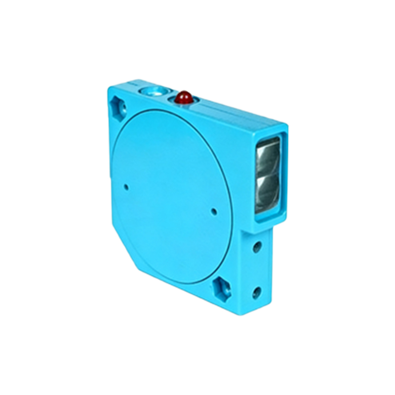
Prior to final electrical connection, mechanically mount the sensor securely using the provided brackets or threaded holes. Proper alignment of the emitter and receiver windows across the U-gap is critical. Even with quick-connect wiring, a misaligned sensor will not function. Use alignment tools or indicators if available. Ensure the target object will reliably break the beam and that the sensor is protected from physical damage, excessive ambient light, and contamination like dust or oil, which may require a specialized model with increased ingress protection (IP) ratings.
Troubleshooting Common Connection Issues
If the sensor fails to operate after quick-connect installation, follow a logical diagnostic sequence. First, re-check wire placement against the diagram. A common error is reversing the brown and blue power wires. Use a multimeter to confirm voltage is present at the sensor terminals. Inspect the quick-connect insertion; a wire may not be fully seated or a stray strand could be causing a short. Verify the output load is functional and correctly connected for the sensor's output type (PNP/NPN). Finally, check the sensing environment for optical obstructions or conditions that could scatter or absorb the light beam.
Advantages of the Quick-Connect System
The adoption of quick-connect wiring in U-shaped photoelectric sensors offers substantial benefits. It drastically cuts installation and replacement time by up to 70%, boosting productivity during machine setup and maintenance. The tool-less (or minimal tool) process standardizes connections, reducing human error and improving first-time-right installation rates. The spring-clamp connection maintains constant force, resisting loosening from vibration—a common failure point in screw terminals. This leads to higher system uptime and long-term reliability. Furthermore, it allows for cleaner control panel layouts and easier modifications without damaging terminal blocks.
Maintenance and Safety Best Practices
Even with a robust connection, periodic inspection is advised. During routine maintenance, visually inspect for signs of corrosion, overheating (discoloration), or loose cables. Always de-energize the circuit before attempting any inspection or disconnection. To remove a wire, insert the screwdriver into the release slot and pull the wire straight out. Avoid excessive bending or pulling on the cables directly at the sensor entry point to prevent strain. Adhering to these practices, along with following all local electrical codes and the manufacturer's instructions, ensures a safe, efficient, and durable sensing solution for automated systems.