Understanding Proximity Sensor Basics
Proximity sensors are essential components in industrial automation, detecting the presence or absence of objects without physical contact. They operate based on electromagnetic, capacitive, or inductive principles, with inductive types being most common for metal detection. Proper wiring is critical to ensure reliable performance and safety. Before starting any wiring process, always refer to the manufacturer's datasheet for specific voltage, current, and connection details. Typically, these sensors have three or four wires, color-coded for easy identification: brown for positive supply, blue for negative or common, black for output signal, and sometimes white for a second output or function.
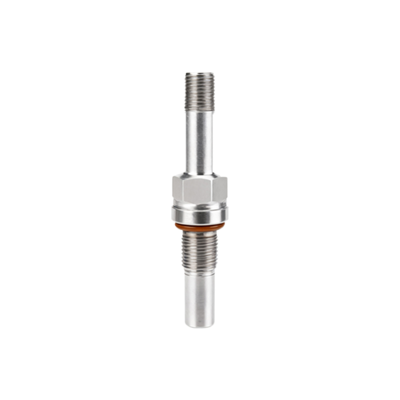
Wiring a 3-Wire DC Proximity Sensor
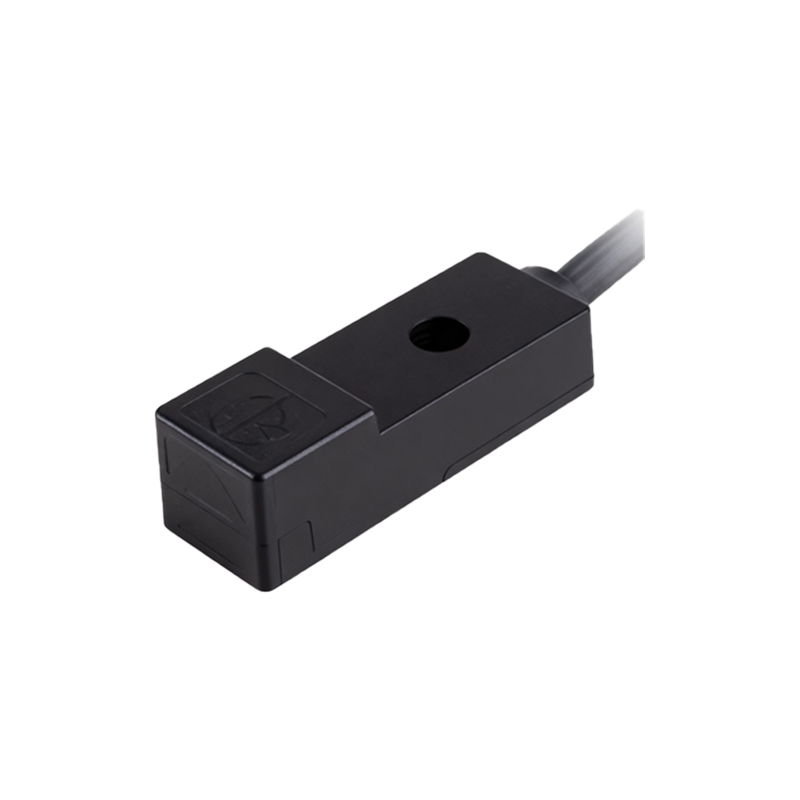
A 3-wire DC sensor is widely used due to its simplicity and effectiveness. Begin by disconnecting power to the circuit to prevent electrical hazards. Identify the wires: brown connects to the positive DC supply (usually +24V), blue to the negative or ground, and black to the load (such as a PLC input or relay). For a normally open (NO) configuration, the black wire outputs voltage when an object is detected. Connect the load between the black wire and ground. Ensure the supply voltage matches the sensor rating, typically 10-30V DC. Use shielded cables in environments with electrical noise, and ground the shield at one end to avoid interference. Test the sensor by bringing a metal target within its sensing range; the output should activate accordingly.
Wiring a 4-Wire DC Proximity Sensor
Four-wire sensors offer additional functionality, often including both normally open (NO) and normally closed (NC) outputs. The wiring follows a similar pattern: brown to positive supply, blue to ground. The black wire is typically the NO output, while the white wire serves as the NC output. Connect the black wire to the load for a signal when an object is detected, and the white wire if you need a signal when no object is present. This setup is useful for fail-safe applications. Double-check the datasheet, as some models may use different color codes or functions. Always secure connections with appropriate terminals to prevent loose wires, which can cause malfunctions or short circuits.
Connecting to a PLC or Controller
Integrating proximity sensors with programmable logic controllers (PLCs) requires attention to input specifications. For a 3-wire sensor, connect the brown wire to the PLC's positive supply terminal, blue to the common ground, and black to the input terminal. Ensure the PLC input type (sourcing or sinking) matches the sensor output. Sourcing sensors provide positive voltage to the PLC input, while sinking sensors connect the input to ground. Incorrect matching can damage components. Use a separate power supply for the sensor if the PLC cannot provide adequate current. Label all wires clearly for future maintenance and troubleshooting.
Power Supply and Safety Considerations
Selecting the right power supply is crucial for sensor longevity. Use a regulated DC power supply with sufficient current capacity, considering all connected sensors. Incorporate a fuse or circuit breaker in the supply line to protect against overloads. Maintain proper polarity; reversing wires can permanently damage the sensor. For long cable runs, calculate voltage drop to ensure the sensor receives adequate voltage. Install sensors away from high-voltage cables or motors to minimize electromagnetic interference. Regularly inspect wiring for wear or corrosion, especially in harsh industrial environments.
Troubleshooting Common Wiring Issues
If a proximity sensor fails to operate, start by checking the power supply with a multimeter to confirm correct voltage. Verify all connections are tight and correct according to the wiring diagram. Inspect for damaged wires or shorts. If the sensor outputs erratically, consider environmental factors like temperature extremes or contamination. For noise-related problems, ensure proper shielding and grounding. Test the sensor independently by connecting it directly to a power supply and load to isolate the issue. Document any changes or repairs for future reference.
Best Practices for Installation and Maintenance
Follow industry standards for installation to maximize sensor performance. Mount sensors securely using brackets to avoid vibration-induced failures. Adjust the sensing distance as per the application needs, keeping a margin for object variations. Clean the sensor face regularly to prevent false triggers from dust or debris. Keep a log of sensor performance and wiring diagrams for quick troubleshooting. Train personnel on proper handling and wiring procedures to reduce errors. By adhering to these guidelines, you can ensure reliable and efficient operation of proximity sensors in any automation system.