Understanding the 4-Wire Photoelectric Sensor
A 4-wire photoelectric sensor is a sophisticated device used extensively in industrial automation for object detection, positioning, and counting. Unlike simpler 2-wire sensors that are directly integrated into the power loop, or 3-wire sensors with separate power and output lines, the 4-wire configuration offers distinct advantages. It typically comprises two wires for the power supply (usually DC voltage like 12-24V DC) and two wires for the output signal. This separation allows for more complex output configurations, most commonly featuring both a Normally Open (NO) and a Normally Closed (NC) contact from a single device. This dual-output capability provides greater flexibility in control logic design, enabling engineers to tailor the sensor's response to specific application requirements without needing additional components.
Identifying the Wiring Configuration
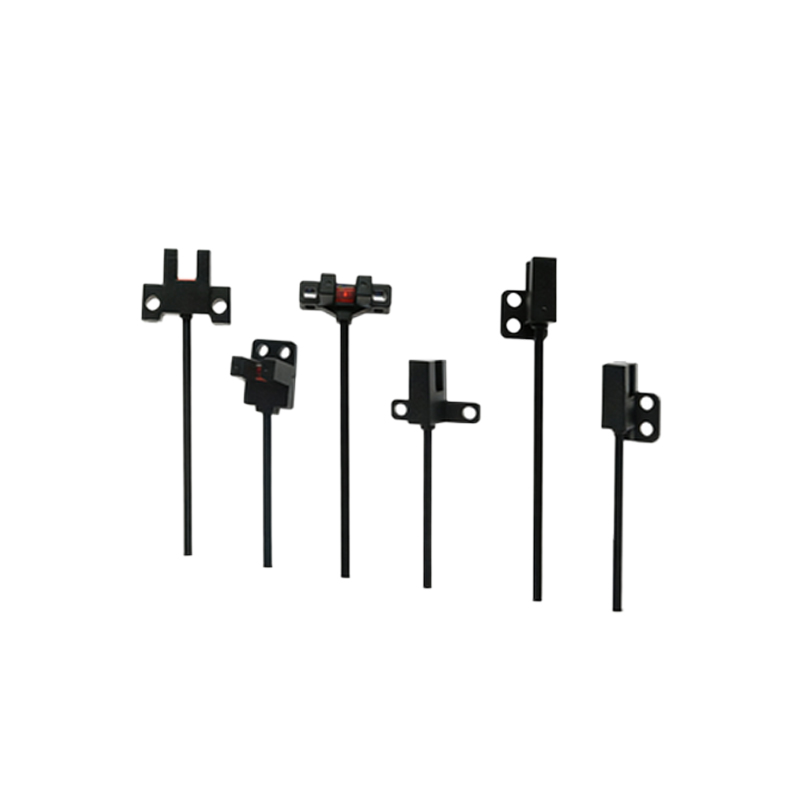
The first step in determining a sensor's functionality is to correctly identify its wiring. Consult the manufacturer's datasheet or the label on the sensor housing. Typically, the wires are color-coded: Brown (or Red) is for the positive DC supply voltage (+V), Blue (or Black) is for the common negative or 0V. The remaining two wires, often Black and White, are for the output signals. The Black wire usually corresponds to the Normally Open (NO) output, and the White wire to the Normally Closed (NC) output. It is crucial to verify this, as color codes can vary between manufacturers. Incorrect wiring can lead to sensor malfunction or damage. Always ensure power is disconnected before handling wires.
Testing Power Supply and Basic Operation
With the power wires correctly connected to a suitable DC power source (e.g., 24V DC), the sensor's indicator LED should illuminate, signaling that it is powered. The behavior of this LED is key. A steady light often indicates power and readiness. Next, observe the output indicator, which is usually a separate LED. Without a target in the sensing range, the output state is in its "normal" condition. For the NO output, this means the circuit is open (off); for the NC output, the circuit is closed (on). Introduce a valid target object into the sensor's detection field. The output indicator LED should change state. For an NO output, the LED will turn on when the target is detected, signaling the output switch has closed. For an NC output, the LED will turn off, signaling the output switch has opened.
Verifying Output Signals with a Multimeter
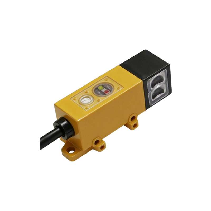
Visual LED indication is helpful, but electrical verification is essential for integration into a control system like a PLC (Programmable Logic Controller). Use a digital multimeter set to measure DC voltage. With the sensor powered and connected, measure the voltage between the NO output wire (e.g., Black) and the common negative (Blue). In the normal state (no target), you should measure near the full supply voltage (e.g., 24V), indicating an open circuit. When a target is detected, the voltage should drop to nearly 0V (a few millivolts), indicating the switch has closed and is sinking current. Conversely, for the NC output wire (e.g., White), measure its voltage relative to common negative. With no target, it should read near 0V (switch closed). When a target is detected, the voltage should rise to near the supply voltage (switch open). This "switching" behavior confirms the sensor's logic.
Assessing Sensing Modes and Range
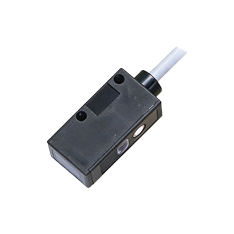
Photoelectric sensors operate in different modes: through-beam, retro-reflective, and diffuse (proximity). Determining the mode is vital. A through-beam sensor has separate emitter and receiver units; blocking the beam triggers detection. A retro-reflective model has both in one housing and requires a reflector; breaking the beam to the reflector triggers it. A diffuse sensor detects light reflected directly from the target. Test the effective sensing range by moving a standard target toward and away from the sensor. Note the point where the output reliably switches. Compare this to the specified range in the datasheet. Environmental factors like target color, material, ambient light, and dust can affect performance, so testing under actual or simulated conditions is recommended.
Integrating with a Control System
The final determination of functionality involves connecting the sensor to its intended load, typically the input module of a PLC or a relay. Connect the sensor's common wire (Blue) to the PLC's common input terminal. Connect the chosen output wire (NO or NC) to a specific PLC input point. Configure the PLC input card accordingly (sourcing vs. sinking). When the sensor detects a target and its output switch activates, the corresponding input LED on the PLC should illuminate, and the input status in the PLC software should change from 0 to 1 (or vice-versa, depending on logic). This confirms not only the sensor's operation but also the integrity of the entire electrical connection and the correct interpretation of the signal by the control logic. Systematic testing under various operational scenarios completes the functional assessment.