Introduction to Photoelectric Sensor Symbols
In the realm of industrial automation and electrical engineering, schematic diagrams serve as the universal language. These diagrams utilize standardized symbols to represent various components, allowing engineers and technicians across the globe to understand, design, and troubleshoot complex systems efficiently. Photoelectric sensors, critical devices for detection, positioning, and counting, have their own distinct set of symbols. Understanding these symbols is fundamental for anyone involved in creating or interpreting electrical drawings, ladder logic, or pneumatic/hydraulic schematics. The symbols convey not just the presence of the sensor but also its specific type, light source, output configuration, and sometimes its physical form factor, providing a wealth of information at a glance.
Core Symbol Structure and Common Elements
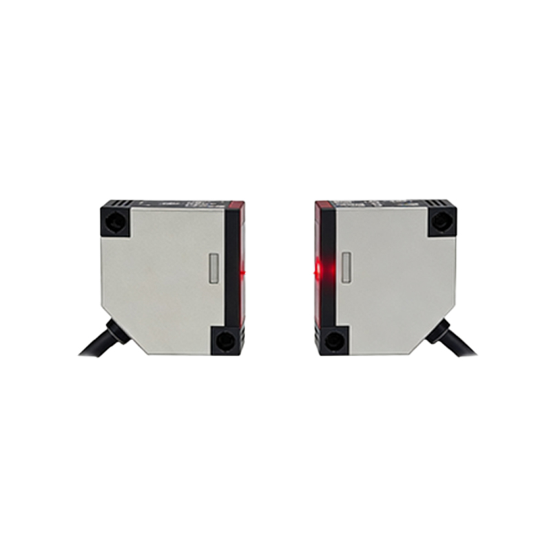
The basic graphical representation of a photoelectric sensor in an electrical diagram typically consists of two main parts: the emitter (light source) and the receiver (detector). These are often depicted as two separate symbols connected by a dashed or dotted line, representing the beam of light. The emitter is commonly shown as a diode symbol with arrows pointing away from it, indicating light emission. The receiver is usually symbolized by a phototransistor or photodiode symbol. A key element is the enclosure shape that often surrounds these components. A rectangle or square is the most generic enclosure. However, symbols may be enclosed in a circle to represent a cylindrical barrel-style sensor or a specific shape indicating a rectangular housing. The connection points, or pins, are shown for power supply, output signal, and sometimes diagnostic or timing functions.
Through-Beam Sensor Symbols
Through-beam (or thru-beam) sensors have separate, opposing units for the emitter and receiver. In schematic diagrams, this is clearly indicated by two distinct symbols placed apart, with the dashed light beam line connecting them. The emitter symbol is on one side, and the receiver is on the other. The receiver's output symbol will change based on its logic. A receiver symbol with a normally open (NO) contact inside its enclosure indicates a "light-on" or "dark-on" operation depending on the design standard. Often, the letters "Tx" (Transmitter) and "Rx" (Receiver) are placed near the respective symbols for absolute clarity. This symbol setup explicitly informs the reader that alignment is critical and that the sensor requires mounting on two sides of the target area.
Retroreflective Sensor Symbols
The symbol for a retroreflective sensor combines the emitter and receiver into a single unit symbol. A single enclosure, often rectangular or circular, contains both the emitting and receiving elements. The key differentiator is the graphical representation of a reflector. A small, stylized triangle or a rectangular block is drawn opposite the sensor symbol, connected by the dashed light beam line. This triangle symbolizes the retroreflector (corner cube reflector). This tells the diagram reader that the sensor and reflector are installed as a pair, with the beam bouncing back from the reflector. The output logic symbol inside the main enclosure again defines its operating mode (e.g., activated when the beam is broken).
Diffuse (Proximity) Sensor Symbols
Diffuse or proximity photoelectric sensors are represented by a single, unified symbol as they house both emitter and receiver. The distinguishing feature is the absence of a separate reflector symbol. Instead, the dashed light beam line curves from the sensor face and returns to it, forming a "U" or loop shape. This curved beam path symbolizes that the sensor detects light reflected directly off the target object itself. The symbol may include wavy lines or a small "bounce" icon near the target area to emphasize the diffuse reflection principle. This is a crucial visual cue, indicating the sensor requires only one mounting point and detects objects at a defined sensing range.
Output Configuration and Electrical Notation
Beyond the optical type, the sensor symbol must convey its electrical output type. This is typically done using standard electrical contact symbols inside or adjacent to the sensor's enclosure. A switch symbol represents a digital output. A switch that is open when the sensor is inactive denotes a normally open (NO) output. A filled-in (dark) triangle attached to the output line universally signifies an NPN (sinking) transistor output. An empty (white) triangle signifies a PNP (sourcing) output. For analog or IO-Link sensors, the symbol may include a wave symbol or the specific notation "IO-Link." The power supply connections, usually labeled as +V (or 24V) and 0V (or GND), are also clearly shown.
Special Function and Enhanced Sensor Symbols
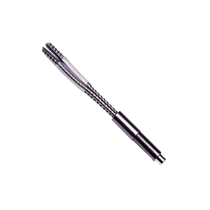
Modern photoelectric sensors come with advanced functionalities, and their symbols reflect these features. A sensor with a background suppression function might have the letters "BGS" or a special marker within its symbol. Color recognition or contrast sensors may include a small color spectrum bar. Fiber optic sensors, which use a photoelectric amplifier, show a distinct symbol for the amplifier unit (similar to a standard sensor) with lines leading to separate symbols for the fiber optic cables and tips. Safety-rated sensors (e.g., Type 4) are often enclosed in a square with a thick border or accompanied by a specific safety symbol. Laser sensor symbols might include a small stylized laser warning icon or the notation "Laser Class."
Importance in System Design and Documentation
Correct usage of photoelectric sensor symbols is not merely a drafting formality; it is essential for accurate system design, clear communication, and effective maintenance. A well-drawn diagram allows for quick identification of sensor types during the panel layout and field wiring phases. It enables troubleshooting teams to understand the expected behavior without referring to multiple datasheets. Furthermore, in programmable logic controller (PLC) programming, the sensor's symbolized logic (NO/NC, PNP/NPN) directly informs the input card wiring and ladder logic contact usage. Consistent application of these symbols per standards like IEC 60617 or ANSI/IEEE Std 91 is a hallmark of professional engineering documentation, reducing errors and ensuring interoperability in global projects.