Understanding the Core Function and Types
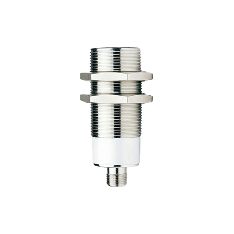
Before putting pen to paper—or cursor to CAD software—a clear understanding of the proximity sensor's function is paramount. A proximity sensor detects the presence or absence of an object within a specified range without physical contact. The schematic must accurately represent this non-contact sensing principle. The first critical step is identifying the sensor type, as the core circuitry differs significantly. The most common types are Inductive (for detecting metallic objects), Capacitive (for detecting both metallic and non-metallic objects), and Photoelectric (using a light beam). An inductive sensor schematic, for instance, will center around an oscillator coil and detection circuit, while a photoelectric sensor will feature an LED emitter and phototransistor or photodiode receiver. Defining the operating principle dictates all subsequent component choices and connections.
Defining Power Supply and Signal Output Requirements
The power supply section is the foundation of any reliable sensor schematic. Clearly specify the voltage range (e.g., 10-30 VDC) and polarity. Incorporate necessary protection components directly at the power input terminals. These typically include a polarity protection diode, a series resistor for current limiting, and a smoothing capacitor to filter out line noise and voltage spikes. Equally crucial is defining the output configuration. The three primary output types are NPN (sinking), PNP (sourcing), and Analog (0-10V or 4-20mA). For a digital NPN output, the schematic will show an NPN transistor with its collector connected to the load and emitter to ground (0V). A PNP output schematic reverses this, with the emitter to positive supply. The output stage must be clearly labeled, and the load (e.g., a PLC input, relay coil) should be indicated in the drawing notes.
Drawing the Sensing Element and Oscillator Circuit
For inductive and capacitive sensors, the heart of the schematic is the oscillator circuit. This circuit generates a high-frequency electromagnetic field from the sensor's face. In an inductive sensor, this involves drawing an LC tank circuit, where 'L' represents the sensing coil. Use the standard inductor symbol and often denote it as the "Oscillation Coil." The capacitor in this tank circuit is part of the feedback network that sustains oscillation. A change in the electromagnetic field (caused by a target) dampens the oscillation. This change is what the detection circuit monitors. This section requires precise component values (though sometimes generalized in a block diagram) and clear connections to the power rails and the subsequent amplifier/detector stage.
Integrating the Signal Conditioning and Detection Stage
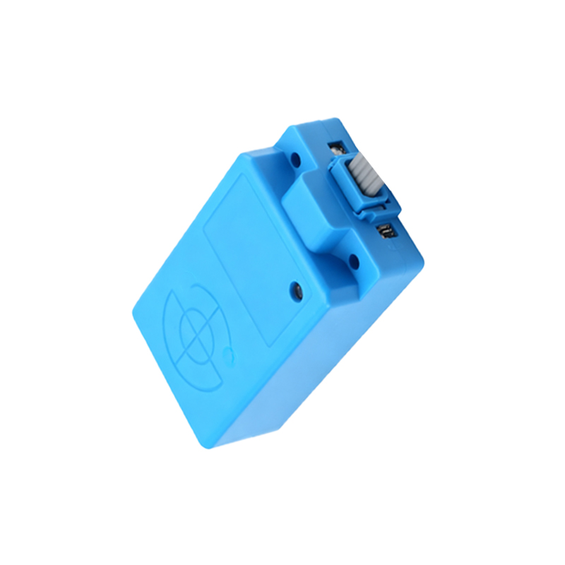
The damped oscillation signal from the sensing coil is weak and requires conditioning. This stage typically includes an amplifier to boost the signal level. Following amplification, a demodulator or peak detector circuit converts the AC oscillation signal into a smooth DC voltage. This DC voltage is then fed into a comparator circuit. The comparator is a key component; it compares the conditioned sensor signal against a preset reference voltage (the sensitivity threshold). Use the standard comparator symbol (triangle). When the sensor signal exceeds (or falls below) this threshold, the comparator's output state changes, triggering the output stage. Clearly show the potentiometer or fixed resistor network that sets this reference voltage, as it controls the sensor's sensing distance.
Adding Status Indication and Protection Circuits
A professional schematic includes auxiliary circuits for functionality and robustness. Almost all industrial proximity sensors feature a Light Emitting Diode (LED) for status indication. This LED is connected, typically via a current-limiting resistor, to illuminate when the sensor is powered (power ON LED) and/or when an object is detected (switching LED). Its placement in the schematic, often parallel to the output transistor, must be clear. Furthermore, incorporate protection components. An output protection diode (free-wheeling diode) should be placed across the load if it is inductive (like a relay coil) to suppress voltage spikes. Consider adding a metal-oxide varistor (MOV) or Transient Voltage Suppression (TVS) diode at the power input for surge protection, especially for sensors used in harsh electrical environments.
Applying Schematic Conventions and Final Review
Adherence to universal electronic schematic conventions is non-negotiable for clarity. Use distinct and standard symbols for all components (resistors, capacitors, transistors, ICs, diodes). Label every component with a unique designator (e.g., R1, C2, Q1, U1) and, where practical, note its critical value (10kΩ, 100nF). Organize the schematic logically: power input on the left, sensing element at the top, signal flow left-to-right, and