Understanding E2B Proximity Sensor Fundamentals
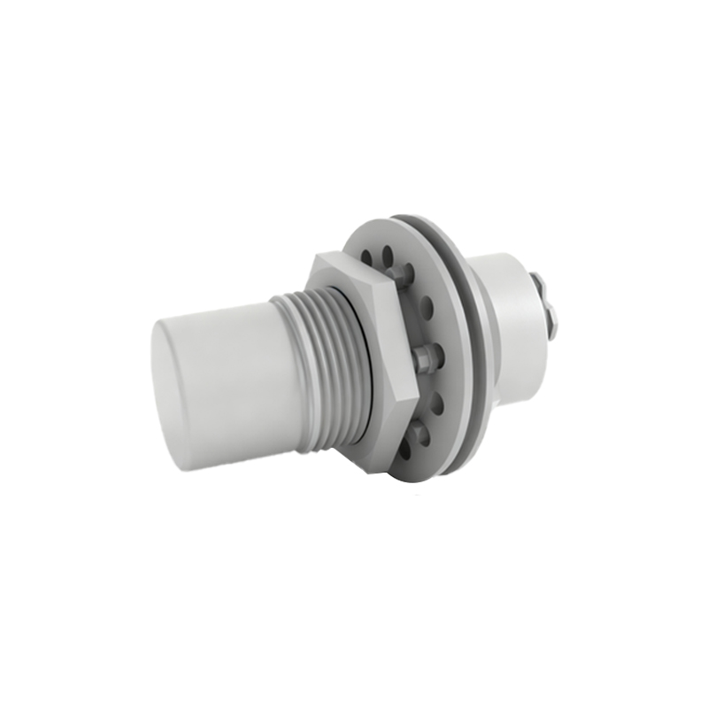
E2B proximity sensors are widely used in industrial automation for non-contact detection of metallic objects. Before beginning any wiring procedure, it is crucial to identify the specific model type. E2B sensors primarily come in two-wire (AC), three-wire (DC), and four-wire (dual-channel) configurations. The sensor's body is typically marked with its type, operating voltage (e.g., 10-30V DC or 90-250V AC), output type (NPN or PNP for DC, and Normally Open/Closed for AC), and current rating. Always consult the manufacturer's datasheet for the exact specifications of your sensor model. Safety is paramount; ensure all power sources are locked out and tagged out (LOTO) before handling any electrical connections.
Essential Tools and Safety Precautions
Gather the necessary tools including appropriate screwdrivers, wire strippers, crimping tools, and a multimeter for verification. Personal protective equipment (PPE) such as safety glasses and insulated gloves is mandatory. Verify the power supply voltage matches the sensor's requirements precisely. Using an incorrect voltage can permanently damage the sensor or create a hazardous situation. Prepare the correct gauge of shielded cable, as recommended for industrial environments, to minimize electrical noise interference which can cause erratic sensor operation.

Wiring a Two-Wire AC E2B Proximity Sensor
Two-wire sensors are the simplest to connect, functioning similarly to a switch. They are commonly used in AC circuits. One wire is connected to the phase (hot/live) conductor of the AC power supply. The other wire is connected to the load (e.g., a relay coil or PLC input module). The load is then connected to the neutral conductor of the supply, completing the circuit. There is no polarity concern for AC wiring. When a target enters the sensing range, the internal switch closes, allowing current to flow and activate the load. Ensure the load current does not exceed the sensor's maximum switching capacity.
Wiring a Three-Wire DC E2B Proximity Sensor
Three-wire DC sensors are prevalent in modern control systems. They have three distinct wires: brown (or red) for positive supply (+V), blue for negative supply (0V or common), and black (or white) for the output signal. For an NPN type sensor (sinking output), the black wire is connected to the load, and the other side of the load is connected to the positive supply. When activated, the NPN sensor sinks current to the common (blue). For a PNP type sensor (sourcing output), the black wire is also connected to the load, but the other side of the load is connected to the common (blue). When activated, the PNP sensor sources current from the positive supply. Always double-check the wiring diagram on the sensor's label.
Connecting to a Programmable Logic Controller (PLC)
When interfacing with a PLC digital input module, correct wiring is critical. For a DC input card, first identify if it is configured for sinking or sourcing input. Match this with your sensor's output type. For a sinking PLC input (common to +24V), use a PNP sensor. Connect the sensor's brown wire to +24V, blue to the PLC's common (0V), and black to the specific input terminal. For a sourcing PLC input (common to 0V), use an NPN sensor. Connect the sensor's brown wire to +24V, blue to 0V, and black to the PLC input terminal. The PLC input's internal circuit completes the path. Incorrect pairing can lead to malfunction or damage.
Implementing Shielded Cable and Grounding
In electrically noisy industrial environments, proper shielding is non-negotiable. Use a shielded multi-conductor cable. Connect the cable's drain wire or metallic shield to a solid earth ground point at the control panel end only. Do not connect the shield at both ends, as this can create ground loops. The shield should be grounded to the panel's grounding busbar, providing a path for electromagnetic interference (EMI) to dissipate, ensuring stable sensor signal integrity. Keep sensor cables away from high-voltage power lines, motor drives, and welding equipment to further reduce noise induction.
Verification and Troubleshooting Steps
After wiring, perform a systematic verification. Restore power and observe the sensor's indicator LED (if equipped). A steady or blinking LED often indicates power and standby status. Bring a target of the correct material and size into the sensing field. The LED