Understanding the Basic Principle
Reflective photoelectric sensors operate on a straightforward yet elegant principle. They contain both a light emitter, typically an LED, and a light receiver, such as a phototransistor, housed within a single unit. The emitter projects a beam of light towards a target. When this light strikes the target's surface, a portion of it is reflected back towards the sensor. The receiver detects this reflected light and converts it into an electrical signal. The key variable is the intensity of the returned light, which is influenced by the target's distance, color, reflectivity, and surface finish. A highly reflective, light-colored object close to the sensor will return a strong signal, while a dark, matte, or distant object will return a weak one. The sensor's internal circuitry is designed to interpret this signal strength and trigger a switching output (ON or OFF) based on a predefined threshold. This self-contained, opposed-mode design makes reflective sensors compact and easy to install, as they only require wiring on one side, unlike through-beam sensors which need separate emitter and receiver units.
Pre-Installation Considerations and Setup
Before beginning the physical adjustment, proper setup is crucial for optimal performance. First, select the appropriate sensor type for your application. Standard diffuse reflective sensors are common but can be sensitive to background objects and color variations. For more demanding tasks, consider background suppression or polarized retro-reflective sensors which offer better discrimination. Next, ensure the electrical specifications—voltage, current, output type (NPN/PNP, NO/NC)—match your control system. Mount the sensor securely on a stable platform, minimizing vibration. Position it at the approximate required sensing distance, ensuring the target's expected path is within the sensor's declared range. Pay close attention to the sensor's datasheet for its specific sensing characteristics curve. Connect the power and load according to the wiring diagram. It is highly recommended to use the sensor's indicator LED (if available) as a visual aid during the subsequent adjustment phase. This LED typically illuminates when the receiver detects sufficient light, providing immediate feedback.
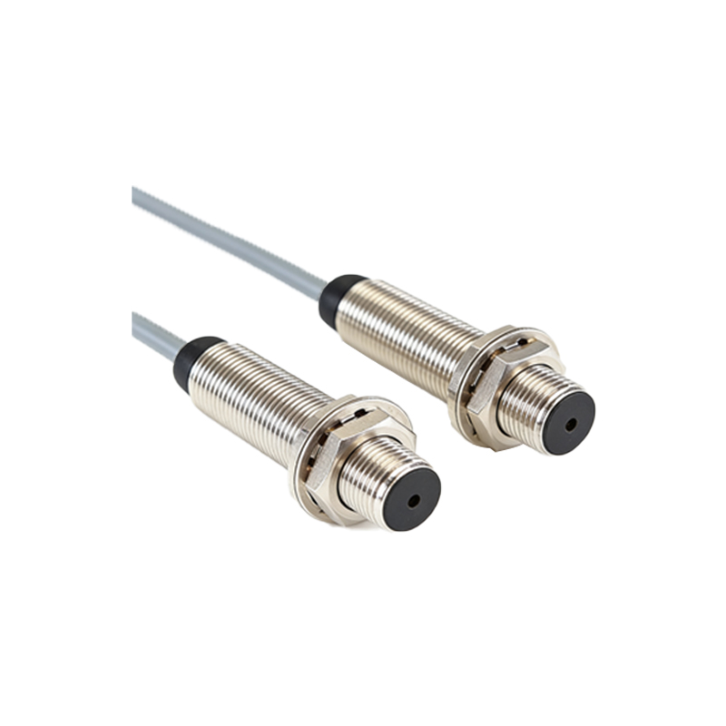
The Core Adjustment Procedure: Sensitivity Potentiometer
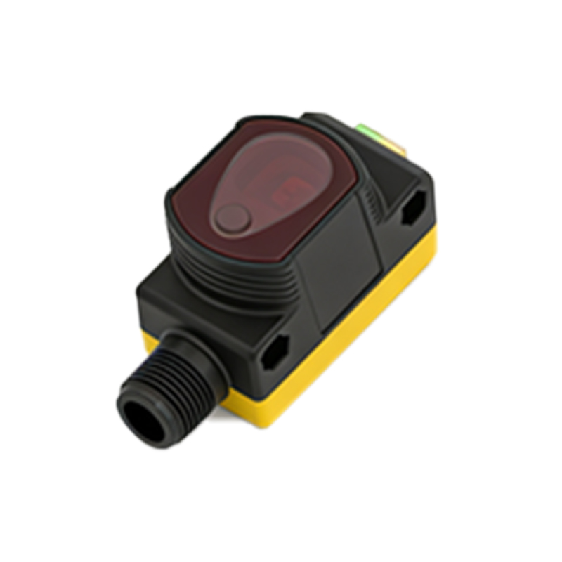
The primary method for tuning a reflective photoelectric sensor is through its sensitivity adjustment, usually controlled by a potentiometer (pot). This pot regulates the threshold level at which the sensor's output switches. The procedure is iterative. Begin by placing the target object in its nominal detection position—the position where you reliably want the sensor to detect it. With the target present, slowly rotate the sensitivity potentiometer. Initially, you will likely be in one of two states: the output is constantly ON (over-sensitive) or constantly OFF (under-sensitive). If the output is ON, rotate the pot counterclockwise to decrease sensitivity until the indicator LED just turns OFF. Then, rotate it clockwise very slightly until the LED just turns ON again. This is the point of minimal reliable detection. Conversely, if the output is OFF, rotate the pot clockwise to increase sensitivity until the LED just turns ON. Then, back it off counterclockwise slightly until it turns OFF, and advance again to the ON point. The goal is to find the "edge" of detection for your specific target, providing a stable operating point with a margin of safety.
Addressing Common Challenges and Fine-Tuning
Real-world environments present challenges that require fine-tuning beyond the basic pot adjustment. For sensing inconsistent targets (varying colors or reflectivity), set the sensitivity using the worst-case (least reflective) target to ensure it is always detected. For applications with background interference, place the most problematic background object (like a shiny machine part) behind the target and adjust the sensitivity so the sensor only triggers for the target, not the background. This may require slightly reducing the overall sensitivity. Environmental light noise from sunlight or factory lamps can cause false triggering. Use sensors with modulated light (pulsed LED) and a corresponding receiver tuned to that frequency to reject ambient light. Mechanical alignment is also critical; ensure the sensor's lens is perpendicular to the target's surface for maximum light return. For very small or fast-moving targets, you may need to increase sensitivity and potentially use a sensor with a faster response time. Always perform adjustment tests under actual operating conditions, including expected temperature ranges and voltage fluctuations.
Verification, Testing, and Maintenance
After adjustment, rigorous verification is essential. Test the sensor across the entire range of expected target positions, not just the nominal point. Check for false triggers by introducing non-target objects into the sensing field. Verify the sensor's performance at the minimum and maximum operating voltages. It is good practice to mark the final potentiometer position with paint or a marker for future reference. Document the settings, target specifications, and environmental conditions. For long-term reliability, implement a periodic maintenance schedule. Clean the sensor's lens regularly to prevent dust, oil, or debris from attenuating the light beam, which can lead to detection failures. Inspect the mounting hardware for loosening due to vibration. Re-verify the adjustment during routine maintenance or if the process or target material changes. By following this systematic approach to adjustment, verification, and upkeep, engineers can ensure reflective photoelectric sensors deliver precise, reliable, and long-lasting performance in automated systems.