Introduction to Photoelectric Tachometers
A photoelectric tachometer represents a cornerstone technology in modern industrial speed measurement. Utilizing the fundamental principles of light emission and reception, these non-contact devices provide highly accurate rotational or linear speed data. At its core, the system consists of a light source, typically an LED or laser diode, and a photodetector. As a target, such as a reflective mark on a rotating shaft or a perforated disc, passes through the light beam, it modulates the signal received by the detector. This modulation is converted into electrical pulses, the frequency of which is directly proportional to the speed of the target. The primary advantage lies in its non-invasive nature, eliminating mechanical wear and allowing for measurement on delicate or high-speed machinery without physical load.
Core Working Principles and Components
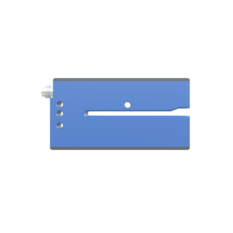
The operation hinges on precise optical detection. Common configurations include through-beam, retro-reflective, and diffuse reflection types. In a through-beam setup, the emitter and receiver are separate units aligned opposite each other; an object passing between them interrupts the beam. Retro-reflective models use a single unit that emits light and receives its reflection from a dedicated reflector, with the target breaking this beam. Diffuse sensors detect light reflected directly off the target itself. The heart of the tachometer is the signal conditioning circuit. It filters noise, amplifies the weak photodetector signal, and shapes it into a clean, digital square wave. This wave is then fed to a microprocessor or frequency-to-voltage converter to calculate revolutions per minute (RPM) or linear velocity, displaying it on a digital readout or transmitting it via industrial communication protocols.
Key Advantages in Industrial Environments
Photoelectric tachometers offer unparalleled benefits for demanding industrial applications. Their non-contact measurement ensures zero slippage and imposes no additional torque load on the system, crucial for testing low-power motors or fragile mechanisms. They provide exceptional accuracy and resolution, often within ±0.05% of reading, making them ideal for calibration and quality control. The high response speed allows them to measure extremely high RPMs, far beyond the capability of mechanical tachometers. Furthermore, they are immune to magnetic fields, a significant limitation of proximity sensors, allowing use near motors and generators. Their versatility extends to measuring both rotational speed and surface linear speed of conveyors, rollers, or moving webs.

Typical Applications Across Industries
The application spectrum for photoelectric tachometers is vast. In manufacturing, they monitor spindle speeds of CNC machines, printing press rollers, and assembly line conveyor belts. The automotive industry relies on them for engine testing, dynamometer systems, and wheel speed analysis. In the pulp and paper sector, they control the speed of massive drying cylinders and winding stations. They are integral to textile machinery for regulating yarn feed rates and in packaging equipment to synchronize operations. Additionally, they serve as critical feedback sensors in closed-loop variable frequency drive (VFD) systems to maintain precise motor speed control, enhancing process stability and energy efficiency.
Critical Selection Criteria and Installation Tips
Selecting the appropriate photoelectric tachometer requires careful consideration of several parameters. First, define the required measuring range (minimum and maximum speed) and the desired accuracy. The response time of the sensor must be fast enough to handle the maximum pulse frequency. The type of target (size, material, color, reflectivity) dictates the choice of sensor model and light source; lasers offer a precise, narrow beam for small targets, while LEDs provide a broader beam. Environmental factors are paramount: consider ingress protection (IP) ratings for dust and moisture, temperature tolerance, and resistance to ambient light interference. Proper installation is crucial: ensure stable mounting to avoid vibration, precise alignment of optical components, and adequate cleaning schedules for lenses to prevent signal degradation from oil or dust accumulation.
Maintenance and Troubleshooting Guidelines
While known for robustness, photoelectric tachometers require periodic maintenance for optimal performance. Regularly clean the emitter and receiver lenses with appropriate solvents to remove grime. Inspect mounting hardware for loosening due to vibration. Common issues include erratic readings or loss of signal. Troubleshooting should start by verifying the power supply and electrical connections. Check for misalignment caused by machine vibration or thermal expansion. Inspect the target for wear, damage, or accumulated debris that might affect reflectivity or beam interruption. Use an oscilloscope to examine the raw pulse signal from the sensor to distinguish between a sensor fault and a problem in the subsequent signal processing circuitry. Ensuring a stable, interference-free electrical environment is also essential.
Future Trends and Technological Advancements
The evolution of photoelectric tachometry is closely tied to advancements in optoelectronics and digital signal processing. The integration of smarter onboard processors enables devices with self-diagnostic capabilities, automatic calibration, and adaptive filtering for noisy environments. Miniaturization continues, allowing sensors to fit into increasingly compact machinery. The adoption of industrial IoT (IIoT) is a significant trend, with tachometers featuring embedded Ethernet, IO-Link, or wireless connectivity for real-time data streaming to cloud platforms for predictive maintenance and analytics. Furthermore, the development of more robust and precise laser diodes expands the viable working distance and allows reliable measurement on low-reflectivity surfaces, pushing the boundaries of non-contact metrology.