Understanding Proximity Sensors and Timer Control Lines
Proximity sensors are widely used in industrial automation for detecting the presence or absence of objects without physical contact. These sensors, including inductive, capacitive, and photoelectric types, generate electrical signals when an object enters their sensing range. Timer control lines, on the other hand, are part of timing devices that manage the duration of operations, such as delaying activation or deactivation of machinery. Connecting a proximity sensor to a timer control line enables automated systems to trigger timed events based on object detection, enhancing efficiency in processes like conveyor belt sorting, machine safety interlocks, or batch processing. This integration requires careful consideration of sensor output types, timer input compatibility, and wiring configurations to ensure reliable performance.
Selecting the Right Components for Connection
Before connecting a proximity sensor to a timer control line, it is essential to verify the specifications of both devices. Proximity sensors typically provide either a digital output (e.g., NPN or PNP transistor-based) or an analog output, with digital being common for timer applications. The timer control line should support the sensor's voltage and current ratings, often ranging from 12V DC to 24V DC in industrial settings. Check the timer's input type—whether it requires a dry contact (switch closure) or a voltage signal—to match the sensor's output. For instance, an NPN sensor sinks current to ground, suitable for timers with sinking inputs, while a PNP sensor sources current, fitting sourcing inputs. Additionally, ensure both devices share a common ground reference to prevent electrical noise or malfunctions.
Wiring Diagram and Step-by-Step Connection Process
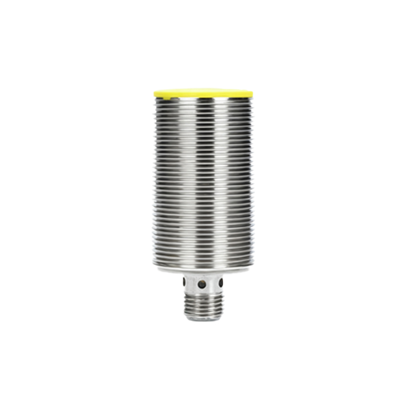
To connect the proximity sensor to the timer control line, follow a systematic wiring approach. First, power off all equipment to avoid electrical hazards. Identify the sensor's output wire (usually brown for positive, blue for negative, and black for signal) and the timer's control input terminals (often labeled as "IN," "COM," or "TRIG"). For a basic setup with a digital sensor and a timer requiring a dry contact, connect the sensor's signal wire to one timer input terminal and link the sensor's negative wire to the timer's common terminal. If using a voltage signal, wire the sensor's output directly to the timer's input, ensuring polarity alignment. Use shielded cables for long runs to minimize interference. After connections, secure wires with terminal blocks and inspect for loose contacts before powering on.
Configuring Timer Settings for Sensor Integration
Once the physical connection is complete, configure the timer to respond appropriately to the sensor's signals. Access the timer's settings via its interface or programming software, depending on the model. Set the timer mode—such as on-delay, off-delay, or interval—based on the desired operation. For example, in an on-delay setup, the timer activates an output after a preset time when the sensor detects an object. Adjust parameters like time duration (e.g., seconds or minutes) and trigger sensitivity to match the application's requirements. Test the configuration by placing an object within the sensor's range and verifying that the timer initiates the expected timing cycle. Fine-tune settings to avoid false triggers or delays, ensuring seamless automation.
Troubleshooting Common Connection Issues
If the system does not function as intended, several troubleshooting steps can resolve common issues. First, check power supply voltages to both the sensor and timer, as low voltage may cause erratic behavior. Verify wiring connections against the diagram, ensuring no crossed or loose wires. Use a multimeter to measure the sensor's output signal when activated; it should match the timer's input requirements (e.g., 0V for off, 24V for on). If the timer fails to trigger, confirm its input compatibility—some timers need a pulsed signal rather than a continuous one. Additionally, inspect for environmental factors like metal interference near inductive sensors or ambient light affecting photoelectric sensors. Resetting the timer to factory defaults and reconfiguring may also address software-related glitches.
Applications and Best Practices in Industrial Use
Connecting proximity sensors to timer control lines finds applications across various industries, including manufacturing, packaging, and automotive assembly. For instance, in a production line, a sensor can detect a product and trigger a timer to control a robotic arm's movement duration. Best practices involve regular maintenance, such as cleaning sensor lenses to prevent false readings, and using surge protectors to safeguard against voltage spikes. Document wiring layouts and settings for future reference, and train personnel on safe handling procedures. By adhering to these guidelines, engineers can optimize system reliability, reduce downtime, and enhance overall operational safety in automated