Introduction to Photoelectric Sensors in Sorting Systems
Photoelectric sensors are pivotal components in modern sorting systems, enabling precise detection and classification of objects across various industries, including logistics, manufacturing, and recycling. These sensors operate by emitting a light beam—typically infrared, visible, or laser—and detecting changes in the received light to identify object presence, position, or characteristics. In sorting applications, they ensure efficiency by automating the process of directing items to designated pathways based on predefined criteria such as size, color, or material. The integration of photoelectric sensors reduces human error, increases throughput, and enhances overall system reliability. Their versatility allows them to adapt to diverse environments, from high-speed conveyor belts to robotic arms, making them indispensable in automated sorting solutions. This article delves into the working principles, illustrated through diagrams, to provide a clear understanding of how these sensors function in sorting contexts.
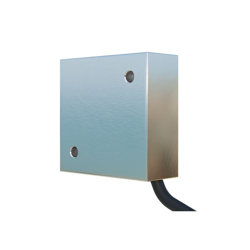
Basic Working Principle of Photoelectric Sensors
At its core, a photoelectric sensor consists of three main components: an emitter, a receiver, and a signal processing unit. The emitter generates a light beam directed toward the target area, while the receiver captures the light that is either reflected from an object or transmitted through it. When an object interrupts or alters the light path, the receiver detects this change and converts it into an electrical signal. This signal is then processed by the unit to trigger an output, such as activating a sorting mechanism. There are three primary sensing modes: through-beam, retro-reflective, and diffuse reflective. In through-beam mode, the emitter and receiver are placed opposite each other, detecting objects that break the beam. Retro-reflective mode uses a reflector to bounce light back to the receiver, with objects interrupting the return path. Diffuse reflective mode relies on light reflecting directly off the object itself. Each mode suits different sorting scenarios, depending on factors like object size, surface texture, and required detection range.
Diagram Analysis: Through-Beam Sensor in Sorting
A through-beam photoelectric sensor diagram typically shows the emitter and receiver aligned on opposite sides of a conveyor belt. The emitter projects a continuous or pulsed light beam across the path to the receiver. When no object is present, the beam reaches the receiver uninterrupted, maintaining a steady signal. As an item moves along the belt and passes through the beam, it blocks the light, causing the receiver to detect a drop in intensity. This interruption triggers the sensor to send a signal to the control system, which can then initiate sorting actions, such as pushing the item off the belt or diverting it via a gate. This mode offers high accuracy and long detection ranges, making it ideal for sorting large or opaque objects in high-speed environments. Diagrams often highlight the alignment precision required to avoid false triggers, emphasizing the importance of proper installation for optimal performance.
Diagram Analysis: Retro-Reflective Sensor for Object Detection
In a retro-reflective sensor diagram, the emitter and receiver are housed in the same unit, facing a reflector placed on the opposite side of the sorting area. The emitter sends a light beam to the reflector, which bounces it directly back to the receiver. When an object enters the sensing field, it obstructs the reflected beam, causing the receiver to note the absence of light. This change prompts the sensor to output a signal for sorting decisions. Retro-reflective sensors are commonly used in sorting systems where space is limited or where through-beam setups are impractical. They provide reliable detection for objects with reflective surfaces, though they may require filters to ignore ambient light interference. Diagrams illustrate the angular alignment between the sensor and reflector, showcasing how even slight misalignments can affect detection reliability, thus underscoring the need for careful calibration in sorting applications.
Diagram Analysis: Diffuse Reflective Sensor in Color Sorting
Diffuse reflective sensors operate by emitting light that reflects off the target object back to the receiver, which is co-located with the emitter. A diagram for this mode often depicts the sensor positioned above a conveyor belt, directing light downward onto passing items. The receiver measures the intensity and quality of the reflected light, which varies based on the object's color, material, or surface properties. In color sorting applications, for instance, sensors can distinguish between different hues by analyzing the wavelength of reflected light, enabling systems to separate items like plastics or agricultural products. This mode is highly effective for close-range detection and can adapt to irregularly shaped objects. Diagrams may include spectral graphs to show how light reflection differs across colors, aiding in understanding how sensors differentiate items for precise sorting.
Advanced Features: Background Suppression and Fiber Optics
Modern photoelectric sensors incorporate advanced features like background suppression and fiber optic elements to enhance sorting accuracy. Background suppression technology allows sensors to ignore objects beyond a set distance, focusing only on items within the sorting zone. Diagrams for this feature show adjustable sensing ranges, with shaded areas indicating ignored backgrounds, preventing false triggers from distant objects or conveyor parts. Fiber optic sensors, depicted with flexible cables transmitting light, enable detection in tight or hazardous spaces where traditional sensors cannot fit. In sorting systems, these are used for small-item detection or in high-temperature environments. Both features improve reliability by minimizing errors, as illustrated in diagrams that contrast standard versus advanced setups, highlighting their role in complex sorting tasks.
Integration with Sorting Control Systems
Photoelectric sensors do not operate in isolation; they integrate seamlessly with broader control systems, such as PLCs (Programmable Logic Controllers) or industrial computers. A system diagram typically shows sensors connected via wiring or wireless networks to a central unit that processes multiple inputs. When a sensor detects an object, it sends data to the control system, which analyzes information like timing, position, and sensor type to execute sorting commands. For example, in a parcel sorting facility, sensors might identify package sizes and direct them to appropriate chutes. Diagrams often include flowcharts or block diagrams to visualize this integration, emphasizing how sensor signals translate into mechanical actions, ensuring synchronized and efficient sorting operations.
Common Applications and Industry Examples
Photoelectric sensors are widely used in sorting applications across various sectors. In e-commerce warehouses, they enable high-speed parcel sorting by detecting box dimensions and routing them to correct lanes. Recycling plants utilize them to separate materials like glass, plastic, and metal based on reflectivity or color. Food processing industries employ sensors for sorting produce by size or quality, removing defective items from production lines. Diagrams in these contexts often showcase real-world setups, such as sensor arrays along conveyor belts or robotic pickers, illustrating how multiple sensors work together for comprehensive sorting. These examples demonstrate the adaptability of photoelectric sensors, driven by their precise detection capabilities, to meet diverse industrial needs.
Maintenance and Troubleshooting Tips
To ensure longevity and accuracy in sorting systems, regular maintenance of photoelectric sensors is essential. Common issues include lens contamination, misalignment, or electrical interference, which can lead to false readings and sorting errors. Diagrams for troubleshooting often highlight key checkpoints, such as cleaning emitter and receiver surfaces, verifying alignment with laser tools, and testing signal outputs with multimeters. Preventive measures, like installing protective housings in dusty