Understanding 2-Wire Photoelectric Sensors
A 2-wire photoelectric sensor is a fundamental component in industrial automation, designed for simplicity and direct integration into control circuits. Unlike 3-wire or 4-wire sensors that require separate power and signal lines, a 2-wire sensor operates in series with the load it controls. It functions essentially as a switch, where the two wires serve both as the power supply path and the switching element. This design makes it highly compatible with traditional relay-based systems and simplifies wiring in applications where space or complexity is a constraint. The sensor modulates its internal impedance to switch the connected load, such as a PLC input, relay coil, or indicator lamp, on or off based on the presence or absence of the detected object.
Core Operating Principle
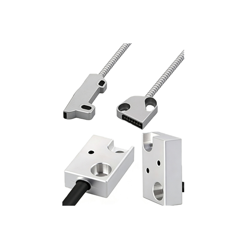
The operational core of a 2-wire DC sensor is based on a solid-state switching device, typically a transistor. When the sensor is in its "off" state (no object detected in the sensing field), it maintains a high impedance, allowing only a small leakage current (often less than 1.5 mA) to flow through the circuit, insufficient to activate the load. Upon detection, the sensor switches to a low-impedance state, allowing the full circuit current (the "load current," e.g., 5-200 mA depending on the model) to flow, thereby energizing the load. It is crucial to note that there is a voltage drop across the sensor (known as the residual voltage or voltage drop, typically 2-5V) when it is conducting. This voltage drop must be subtracted from the supply voltage when calculating the voltage available to the load.
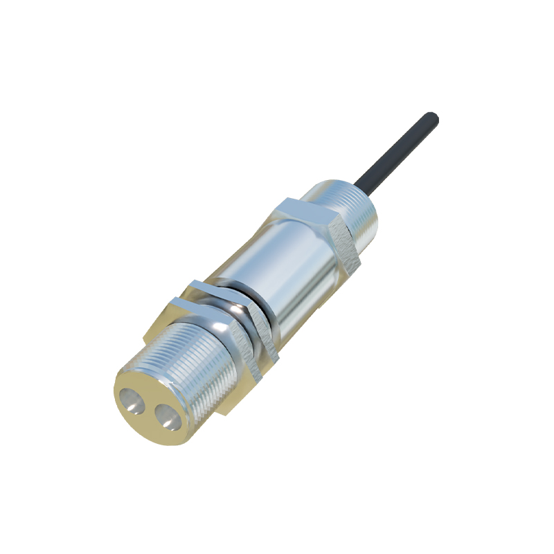
Standard 2-Wire Connection Diagram
The wiring for a 2-wire sensor is straightforward. The following describes a typical setup with a DC power supply:
1. Connect one terminal of the DC power supply (e.g., 24V DC positive) to one wire of the sensor.
2. Connect the other wire of the sensor to one terminal of the load (e.g., the positive input of a PLC digital module, or one side of a relay coil).
3. Connect the other terminal of the load to the opposite polarity of the DC power supply (e.g., 24V DC negative/0V).
This forms a complete series circuit: Power Supply (+) -> Sensor -> Load -> Power Supply (-). Polarity is critical for DC sensors; they must be connected correctly. For AC 2-wire sensors, the wiring is similar, but polarity is not a concern. Always incorporate a fuse or circuit breaker in the supply line for protection.
Key Considerations for Reliable Operation
Several factors are vital for stable performance. First, ensure the power supply voltage matches the sensor's rated voltage (e.g., 10-30V DC). Second, the *load current* must fall within the sensor's specified switching capacity. Exceeding the maximum current can destroy the sensor, while operating below the minimum holding current may cause the load to chatter or not de-energize fully. Third, account for the sensor's *residual voltage*. If the residual voltage is too high relative to the supply voltage, the voltage at the load may be below its minimum operational threshold, causing malfunction. This is particularly important when connecting to PLC inputs with tight voltage thresholds.
Advantages and Limitations
The primary advantage of the 2-wire design is wiring economy and ease of installation, reducing material and labor costs. Its form factor allows for direct replacement of mechanical limit switches. However, limitations exist. The residual voltage can be a drawback in low-voltage circuits. Also, 2-wire sensors generally have lower switching currents compared to 3-wire models and may not be suitable for directly driving heavy loads. The leakage current in the "off" state can sometimes inadvertently hold a very high-impedance load in an active state, requiring careful load selection.
Practical Application Examples
A common application is connecting a 2-wire diffuse photoelectric sensor to a PLC's digital input module. The sensor detects parts on a conveyor. The PLC input, acting as the load, is rated for 24V DC with an input impedance of several kilo-ohms. The sensor's load current specification (e.g., 3-100 mA) comfortably covers the PLC input's required current (typically around 5-10 mA). Another example is using a 2-wire AC sensor to directly control a small pilot lamp or a low-power AC relay for status indication, eliminating the need for an intermediate relay in simple control tasks.
Troubleshooting Common Issues
If the sensor fails to switch the load, first verify power supply voltage and polarity. Measure the voltage across the load terminals when the sensor should be "on"; it should be close to the supply voltage minus the sensor's residual voltage. If it's too low, the load may not activate. Check for insufficient load current; some loads like small relay coils may require a minimum current that the sensor cannot provide in its "on" state. Conversely, if the load remains energized when the sensor is "off," measure the leakage current. It may be exceeding the minimum drop-out current of the load, necessitating a bleeder resistor in parallel with the load to shunt the leakage current away. Always consult the manufacturer's datasheet for specific electrical characteristics.
Selection and Installation Best Practices
When selecting a 2-wire photoelectric sensor, carefully review the electrical specifications: operating voltage range, maximum and minimum load current, residual voltage, and leakage current. Ensure compatibility with the load's electrical characteristics. During installation, use the correct wire gauge for the expected current and provide strain relief. For long cable runs, consider voltage drop in the wires themselves, which adds to the sensor's residual voltage. In electrically noisy environments, proper shielding and grounding of the metal housing (if available) are recommended, even for 2-wire devices, to prevent false triggering. Regularly test the sensor's function under actual operating conditions to ensure long-term reliability.