Understanding Photoelectric Sensor Types
Photoelectric sensors operate by emitting a light beam to detect objects. The three primary types are through-beam, retro-reflective, and diffuse reflective sensors. Through-beam sensors consist of separate emitter and receiver units, offering the longest sensing range and highest reliability. Retro-reflective sensors use a reflector to bounce light back to the receiver, making installation easier while maintaining good range. Diffuse reflective sensors detect objects by receiving light reflected directly from the target, suitable for close-range applications. Selecting the correct type is the foundational step in setup, as each has distinct wiring and alignment requirements. Diagrams illustrating beam paths help visualize how each sensor type interacts with targets and potential obstacles.
Mounting and Mechanical Alignment
Proper mechanical mounting ensures stable operation. Securely fasten the sensor and any reflectors or separate receivers using appropriate brackets. For through-beam sensors, align the emitter and receiver axes precisely. A simple method is to temporarily power the units and observe the alignment indicator LEDs. Adjust until the receiver's "light-on" indicator is stable. For retro-reflective types, align the sensor perpendicular to the reflector center. Avoid mounting surfaces that vibrate excessively. Allow sufficient clearance around the sensor for maintenance and to prevent physical damage from passing objects. Diagrams showing correct versus incorrect mounting angles and clearance distances are crucial for avoiding common installation errors.
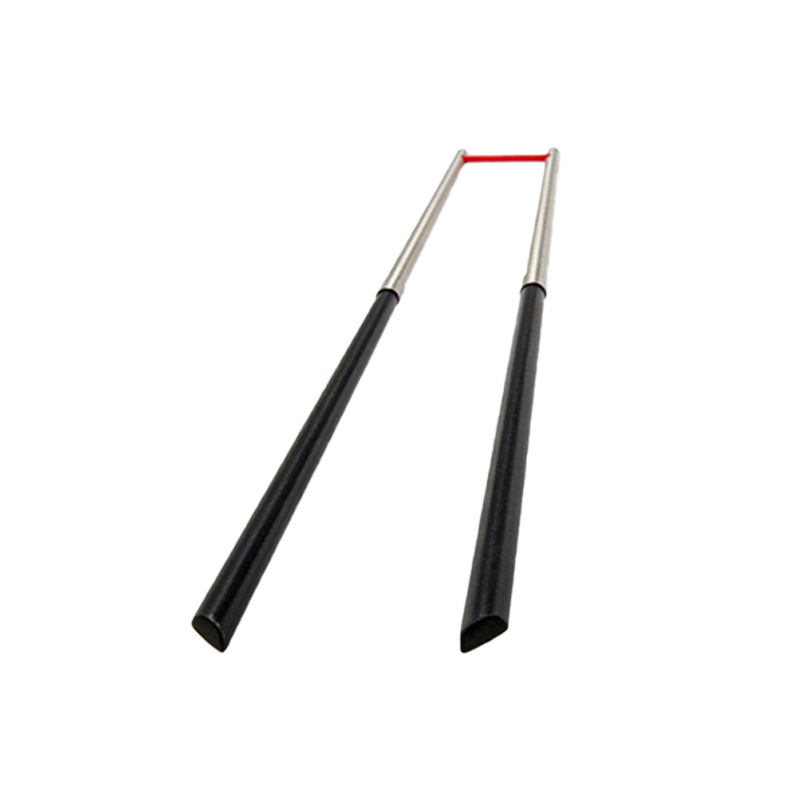
Electrical Wiring and Connection
Refer to the sensor's datasheet for the specific wiring diagram. Most sensors have at least three wires: brown for DC positive, blue for DC common, and black for the output signal. For AC models, typically black and white are for line voltage. Always connect the load (e.g., PLC input, relay) in series with the output wire. Ensure the power supply voltage matches the sensor rating. Use shielded cables in electrically noisy environments, connecting the shield to ground at the controller end only. After wiring, apply power and check the power indicator LED. A wiring diagram with clear labels for power supply, load, and sensor terminals prevents connection mistakes that could lead to sensor damage or erratic operation.
Configuring Sensitivity and Response Time
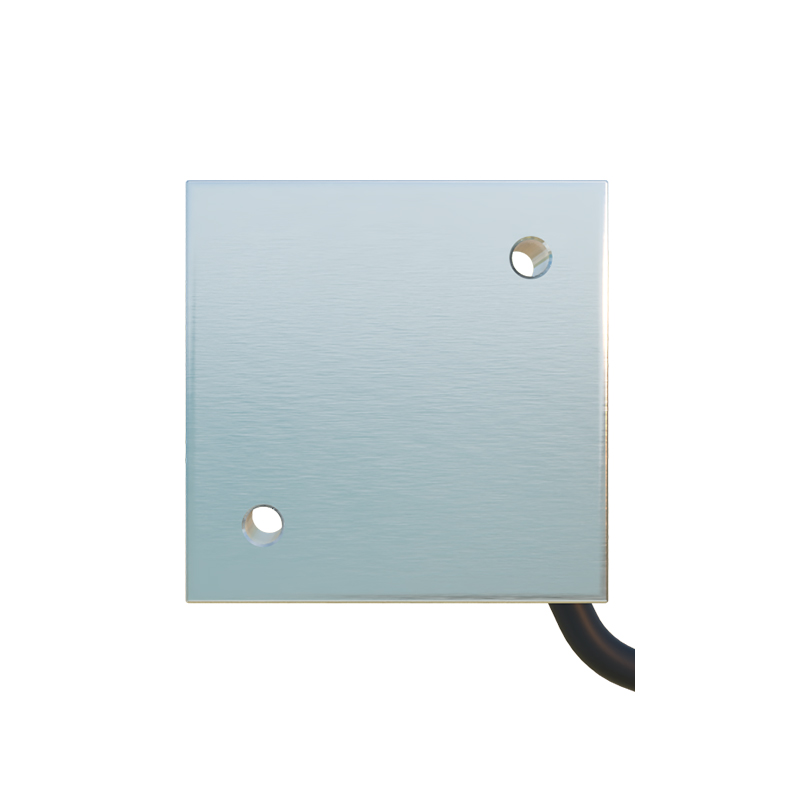
Many photoelectric sensors feature a sensitivity potentiometer or teach-in button. Adjust sensitivity to reliably detect the target while ignoring background objects or dust. For a teach-in sensor, present the standard target at the desired sensing distance and activate the teach function. Set the response time or output delay to match the application speed. A fast response is needed for high-speed counting, while a short delay can help reject vibration-induced false signals. Use the stability indicator, if available, during adjustment. Diagrams showing the location of adjustment controls and their effect on the sensing window aid users in optimizing performance without trial and error.
Beam Alignment Verification Techniques
Even after initial alignment, verify the beam path. For through-beam and retro-reflective sensors, use an alignment card or the sensor's built-in alignment aid. Slowly move a target through the beam while monitoring the output. The sensing range should be consistent. For diffuse sensors, check the maximum detection distance with the intended target material and color, as these factors greatly affect reflectivity. Environmental factors like ambient light or dirt accumulation on the lens can shift the effective beam. Periodic verification, illustrated with a step-by-step diagram, ensures long-term reliability. Document the final alignment settings for future reference.
Troubleshooting Common Setup Issues
If the sensor fails to operate, follow a systematic approach. First, confirm power and indicator lights. If the power light is off, check wiring and voltage. If the power light is on but the output is inactive, check alignment and sensitivity settings. An object placed at the sensing point should trigger the output indicator. Interference from adjacent sensors, highly reflective backgrounds, or strong ambient light can cause false triggering. Diagrams depicting common problems like cross-talk between sensors, specular reflection paths, and insufficient contrast between target and background provide immediate visual guidance for diagnosis and correction.
Application-Specific Setup Considerations
Tailor the setup to the application. For transparent object detection, use a polarized retro-reflective sensor or a through-beam sensor with high-gain receiver. For small object detection, select a sensor with a focused beam and adjust sensitivity precisely. In conveyor applications, consider background suppression diffuse sensors to ignore the conveyor belt. For high-speed counting, enable the sensor's high-speed response mode and minimize external vibration. Always consult the application notes and dimensional diagrams in the manual, which often provide specific mounting distances, beam spread patterns, and timing charts for different use cases, ensuring optimal integration into the system.