Understanding the Core Components
A photoelectric sensor inspection schematic is a vital roadmap for installation, troubleshooting, and maintenance. At its heart, the schematic details the electrical and optical connections between the sensor's core components: the emitter, the receiver, and the control unit. The emitter, typically an LED (often infrared, red, or laser), generates the light beam. The receiver, a phototransistor or photodiode, detects the presence or absence of this beam. The control unit, often an integrated circuit or a programmable logic controller (PLC) interface, processes the receiver's signal and triggers the output switch (NPN or PNP transistor). The schematic precisely illustrates the power supply connections (common DC voltages like 12-24VDC), the load connection, and the status indicator LEDs. Understanding each symbol and connection point on this diagram is the first step in effective sensor validation.
Interpreting Standard Schematic Symbols
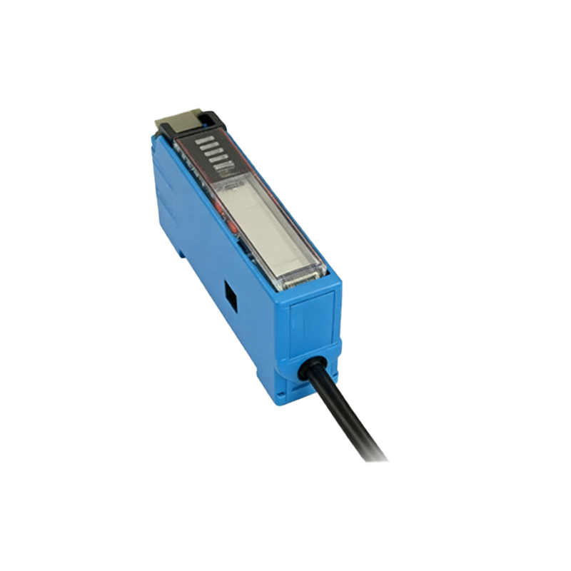
Accurate interpretation hinges on recognizing universal schematic symbols. The emitter is usually represented by a diode symbol with outward-pointing arrows indicating light emission. The receiver is shown as a diode or transistor symbol with inward-pointing arrows. The output switch is depicted as a transistor symbol (for solid-state outputs) or a relay contact. Wires are shown as connecting lines, with junctions marked by a dot. It is crucial to identify the labeling for power terminals (V+ or +V, 0V or COM), output terminals (OUT or LOAD), and, in some models, teach-in or timing function wires. Many schematics also include a simplified drawing of the sensing modes—through-beam, retro-reflective, and diffuse—to clarify the optical path being monitored.
Step-by-Step Inspection Procedure
Begin inspection by verifying the power supply against the schematic's specifications using a multimeter. Incorrect voltage is a primary cause of failure. Next, with power applied, check the status indicator LEDs. A steady or blinking LED on the emitter side often confirms power and operation. On the receiver/controller side, the output state LED should change when the light beam is interrupted (in dark-on mode) or received (in light-on mode). If indicators behave erratically, proceed to signal measurement. Using an oscilloscope on the receiver's signal line (if accessible per the schematic) can reveal the strength and integrity of the received pulse, distinguishing between a weak signal, electrical noise, or a complete failure.
Troubleshooting Common Circuit Failures
The schematic is indispensable for diagnosing specific circuit failures. A constant output regardless of target presence may indicate a shorted output transistor or a failure in the receiver's amplification circuit. No output may point to an open circuit, a damaged emitter, or a misaligned beam breaking the optical path shown in the diagram. Electrical noise interference, manifesting as erratic switching, can often be traced to improper shielding or grounding not per the schematic's recommendations—such as missing ferrite cores or separated cable runs for power and signal lines. Cross-referencing measured voltages at test points with the schematic's expected values quickly isolates the faulty section.
Validating Wiring and Load Compatibility
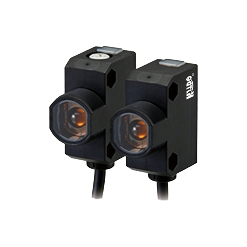
A frequent error is incorrect wiring, which the schematic directly addresses. For a 3-wire DC sensor, ensure the brown wire (typically +V) and blue wire (0V) are connected to the correct polarity. The black (or white) output wire must be connected to the load, which then returns to the opposite power rail. The schematic specifies whether the output is NPN (sinking) or PNP (sourcing); connecting an NPN output to a PNP input circuit will not function. Furthermore, verify the load (relay coil, PLC input, etc.) does not exceed the sensor's maximum current rating, as specified in the accompanying datasheet often referenced by the schematic. An overload can damage the internal output switch.
Advanced Diagnostics and Signal Analysis
For persistent issues, advanced diagnostics using the schematic are required. This involves checking timing circuits for sensors with on-delay or off-delay functions. The schematic will show the connection points for external potentiometers or teach-in wires used to adjust sensitivity or set timing parameters. Using a light power meter to measure the actual emitted light intensity against specifications can identify a degraded emitter. In modulated sensors (to combat ambient light), a frequency counter can verify the emitter's modulation frequency matches the receiver's tuned frequency, a critical alignment not visually apparent but implied in the schematic's block diagram of the control logic.
Preventive Maintenance and Documentation
Finally, the inspection schematic is a cornerstone of preventive maintenance. Regularly comparing current draw against the baseline noted on the schematic can predict impending power supply issues. Keeping a log of environmental factors (like lens contamination shown as a barrier in the optical path diagram) alongside performance metrics helps establish maintenance schedules. Always update system documentation with any wiring modifications, and ensure the schematic used is the correct revision for your sensor model. A well-understood schematic transforms reactive repair into proactive system management, ensuring long-term reliability and minimizing unplanned downtime in automated processes.