Introduction to Photoelectric Sensors
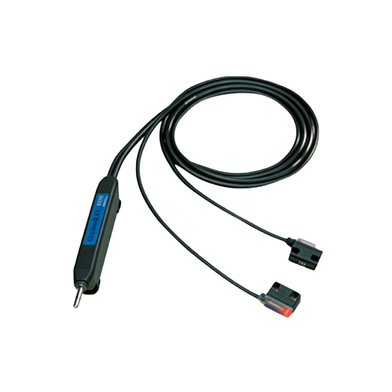
Photoelectric sensors are widely used in industrial automation for detecting objects, measuring distances, and monitoring processes. These sensors operate by emitting a light beam—typically infrared, visible, or laser—and detecting changes in the received light due to the presence or absence of an object. They consist of key components: a light emitter (such as an LED or laser diode), a light receiver (like a phototransistor or photodiode), and supporting circuitry. The receiver converts light intensity into an electrical signal, which is then processed to trigger outputs. However, without proper current limiting or voltage regulation, the sensor's components can be damaged by excessive current or voltage spikes. This is where resistors play a critical role in ensuring reliable and safe operation.
Role of Resistors in Current Limiting
Resistors are essential in photoelectric sensor circuits to limit current flow through sensitive components. For instance, the light emitter—an LED or laser diode—requires a specific forward current to operate efficiently without overheating. If connected directly to a power supply without a resistor, the current could exceed the component's maximum rating, leading to rapid degradation or failure. By placing a resistor in series with the emitter, the current is controlled to a safe level, extending the device's lifespan. Similarly, in the receiver side, phototransistors or photodiodes generate a small current proportional to light intensity. A resistor is often used in series or parallel to convert this current into a measurable voltage signal, while also preventing saturation or damage from high currents in bright conditions.
Voltage Division and Signal Conditioning
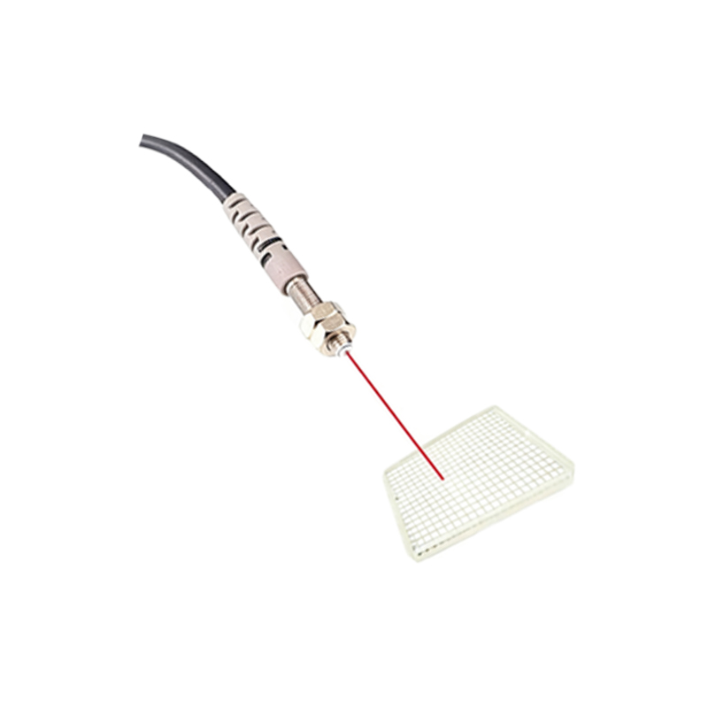
In many photoelectric sensor applications, resistors are employed for voltage division to match signal levels with downstream circuitry. The receiver's output may need to be adjusted to interface with microcontrollers, PLCs, or amplifiers that operate at different voltage ranges. By using a resistor network, the sensor's output voltage can be scaled appropriately, ensuring accurate detection and minimizing noise. Additionally, resistors help in biasing transistors within the sensor circuit, stabilizing the operating point for consistent performance across varying temperatures and environmental conditions. Without proper voltage division, signals might be too weak to detect or too strong, causing false triggers or component stress.
Protection Against Electrical Noise and Surges
Industrial environments often expose sensors to electrical noise, voltage surges, or electromagnetic interference (EMI), which can disrupt sensor operation. Resistors, when combined with capacitors or other components, form filtering circuits that reduce noise and protect sensitive parts. For example, a pull-up or pull-down resistor can ensure the sensor output remains in a defined state when not active, preventing floating signals that lead to erratic behavior. In surge protection, resistors dissipate excess energy from transient voltage spikes, safeguarding the sensor's internal electronics. This is crucial in harsh settings where machinery or power fluctuations are common, enhancing the sensor's durability and reliability.
Calibration and Sensitivity Adjustment
Resistors allow for fine-tuning of photoelectric sensor sensitivity and response time. By adjusting variable resistors (potentiometers) in the circuit, users can calibrate the sensor to detect objects of different reflectivity, sizes, or distances. This adjustability is vital in applications like packaging lines, where sensors must distinguish between various materials or operate in changing light conditions. Fixed resistors set baseline parameters, while potentiometers enable on-site customization without redesigning the entire circuit. Proper calibration ensures optimal performance, reducing false positives and improving system efficiency.
Practical Circuit Examples
Consider a common photoelectric sensor setup: an infrared LED emitter paired with a phototransistor receiver. In the emitter circuit, a series resistor is calculated based on the supply voltage and LED's forward voltage and current. For a 12V supply and an LED with 2V forward voltage and 20mA current, a 500-ohm resistor limits the current appropriately. In the receiver circuit, a load resistor connects the phototransistor's collector to the supply, converting the photocurrent into an output voltage. Values like 10k ohms are typical, balancing sensitivity and response speed. These examples highlight how resistors are integral to functional designs, ensuring both protection and accurate signal processing.
Conclusion and Best Practices
Integrating resistors into photoelectric sensor circuits is not optional but a fundamental aspect of electrical design. They provide current limiting, voltage regulation, noise reduction, and calibration capabilities, all of which contribute to the sensor's accuracy and longevity. When designing or installing these sensors, always refer to datasheets for component specifications and calculate resistor values precisely. Use high-quality, temperature-stable resistors to maintain performance in industrial settings. By understanding and applying these principles, engineers can optimize photoelectric sensors for diverse applications, from simple object detection to complex automated systems, ensuring reliable operation and minimizing downtime.