Understanding Proximity Sensor Fundamentals
Before writing a single line of code, it is crucial to understand the type of proximity sensor being used. Inductive sensors detect metallic objects, capacitive sensors detect both metallic and non-metallic materials, and ultrasonic or photoelectric sensors use sound or light waves. Each type generates a different output signal—typically a digital ON/OFF signal (PNP or NPN sourcing/sinking) or an analog voltage/current signal proportional to distance. The core programming logic revolves around reliably reading this signal. The first step is always to consult the sensor's datasheet to confirm its operating voltage, output type, current rating, and response time. This foundational knowledge directly informs the hardware interface design and the subsequent software architecture.
Hardware Interface and Microcontroller Setup
The program's reliability starts with a correct physical connection. For a digital sensor, connect the output wire to a digital input pin on your microcontroller (e.g., PLC, Arduino, Raspberry Pi). Incorporate a pull-up or pull-down resistor if necessary, as defined by your circuit design. For analog sensors, connect the output to an analog input pin. Always ensure a common ground between the sensor and the controller. Power the sensor from a stable supply, often the same source as the controller, while being mindful of total current draw. In industrial PLC environments, the sensor is wired to a designated input module. The key programming task here is to correctly configure the microcontroller's pins. For a digital input, set the pin mode toINPUT. For an analog input, ensure the ADC (Analog-to-Digital Converter) is initialized, often requiring a reference voltage setting.
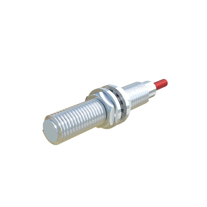
Core Digital Sensor Reading Logic
Reading a digital proximity sensor is fundamentally about polling or interrupting on a state change. In a simple polling loop, the program continuously checks the digital pin's status. For instance, in an Arduino-like environment:int sensorState = digitalRead(SENSOR_PIN);. ThissensorState (HIGH or LOW) is then used in conditional statements to trigger actions like turning on an LED, activating a relay, or incrementing a counter. However, for faster response and efficient CPU use, employ interrupts. Attach an interrupt service routine (ISR) to the pin to handle the change immediately. For a PLC, the digital input is typically mapped directly to a memory bit (e.g., I0.0). The ladder logic or structured text program then uses this contact (normally open or closed) in its control rungs to energize outputs or set internal flags.
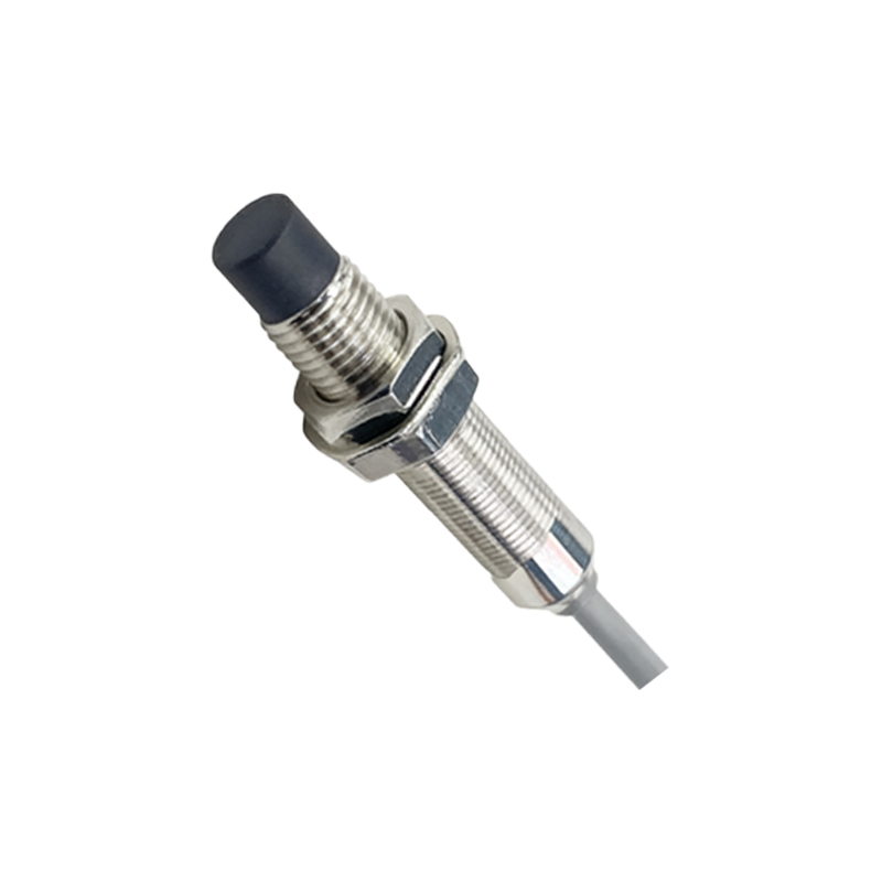
Processing Analog Sensor Data
Analog sensors require an additional step of converting the raw ADC reading into a meaningful distance value. First, read the raw analog value:int rawValue = analogRead(ANALOG_PIN);. This value, say between 0 and 1023, corresponds to a voltage between 0V and the reference voltage. The datasheet provides the transfer function—the relationship between distance and output voltage/current. A common function is inverse proportional. The program must implement this conversion, often involving scaling and mapping. For example:float distance = (k1 / rawValue) - k2; where k1 and k2 are calibration constants. To improve stability, implement software filtering like a moving average or a median filter to smooth out noise from the analog signal before performing the conversion.
Implementing Debouncing and Error Handling
Proximity sensors in noisy industrial environments can produce signal chatter—rapid, false ON/OFF transitions. Software debouncing is essential. For a digital sensor, upon detecting a state change, introduce a short delay (e.g., 10-50ms) and then read the pin again to confirm the state is stable. A more robust method uses timers to track stable state duration. Error handling is critical for reliability. The program should include timeouts for sensor response. For analog sensors, implement range checking; if the converted distance is outside plausible minimum/maximum limits, flag a sensor fault. Always include initialization checks to verify the sensor is responding within expected parameters at startup.
Structuring the Control Program
Move beyond simple reading into a structured application. Define clear functions or routines:initSensor(),readSensor(),filterData(),calculateDistance(),checkFaults(). This modular approach enhances code readability and maintainability. In a state machine design, the sensor input becomes a trigger for state transitions. For example, a machine state might change from "IDLE" to "LOADING" when a part is detected. In PLC programming, this structure is inherent in the ladder logic or function block diagrams.