Understanding Proximity Sensor Wiring Fundamentals
Proximity sensors are indispensable components in modern industrial automation, providing non-contact detection of metallic or non-metallic objects. Among various configurations, the 4-wire proximity sensor stands out for its versatility, combining both normally open (NO) and normally closed (NC) switching functions along with a dedicated power supply pair. This design allows for more complex control logic and failsafe implementations compared to 2-wire or 3-wire variants. The four wires typically consist of two for power (brown for positive, blue for negative/common) and two for output signals (black for NO, white for NC). Proper connection is critical not only for functionality but also for ensuring operational safety, preventing electrical noise interference, and maximizing sensor lifespan. Engineers must first verify the sensor's specifications, including operating voltage (commonly 10-30V DC), output type (PNP or NPN sinking/sourcing), and current rating, before proceeding with installation.
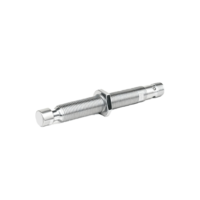
Step-by-Step 4-Wire Connection Procedure
Begin by de-energizing the control circuit to eliminate shock hazards. Identify the wires according to the manufacturer's datasheet: the brown wire connects to the positive DC supply terminal, while the blue wire links to the DC common or negative terminal. For the output side, the black wire (NO contact) and white wire (NC contact) must be connected to the load or controller input modules. In a typical PNP (sourcing) configuration, the black NO wire supplies positive voltage to the load when an object is detected, with the load's other terminal connected to common. Conversely, in an NPN (sinking) setup, the black wire sinks current to common upon detection. The white NC wire operates inversely—it conducts when no target is present. Always use shielded cables for long runs, grounding the shield at the controller end to mitigate electromagnetic interference. After connections, secure wires with cable glands and perform insulation resistance tests.
Differentiating PNP and NPN Output Configurations
Selecting between PNP and NPN output types is a fundamental decision in 4-wire sensor integration. PNP sensors, often called "sourcing" sensors, switch the positive supply to the load; their output wires become positive when activated. They are preferred in Europe and for PLC sinking input modules. NPN sensors, or "sinking" sensors, switch the negative side, connecting the load to common when triggered, and are common in Asian markets and for PLC sourcing inputs. The 4-wire sensor's advantage is that it provides both NO and NC contacts for either type, allowing flexible fail-safe design. For instance, in a safety circuit, the NC contact can be used to halt machinery if the sensor fails. Engineers must ensure compatibility with the control system's input circuit polarity to avoid damage. Diagrams showing current flow from supply through sensor to load should be consulted during design.
Practical Applications and Circuit Examples
In industrial settings, 4-wire proximity sensors enable advanced functions like dual-state monitoring or redundant switching. A classic application is in conveyor systems where both presence and absence of an object must trigger different actions—using NO output to count items and NC to detect jams. Another example is in safety interlocks, where the NC circuit ensures a machine stops if the sensor is disconnected. For wiring, consider a DC 24V system: connect brown to +24V, blue to 0V. The black NO wire might go to a PLC's digital input, while the white NC wire could drive an alarm lamp. If the sensor detects metal, the black wire energizes the PLC input, and the white wire breaks the alarm circuit. For bidirectional control, both outputs can connect to separate controller channels. Always add protective devices like fuses or surge suppressors near the sensor to guard against voltage spikes, especially in environments with inductive loads like solenoids or motors.
Troubleshooting Common Connection Issues
Even with correct wiring, issues may arise. If the sensor fails to respond, first check power supply voltage with a multimeter—it should be within the sensor's range under load. Incorrect polarity can damage sensors; verify brown/blue connections. For erratic operation, inspect for electrical noise from nearby motors or frequency drives; improve grounding or relocate cables. If only one output works, test the NO/NC contacts separately by monitoring their voltage states relative to common. Remember, in a 4-wire sensor, both outputs share a common internal switch mechanism, so a internal fault might affect both. LED indicators on the sensor housing help diagnose status: steady on for power, flashing for detection. Also, ensure the sensing distance and