Introduction to BD2-S3 Proximity Sensor
The BD2-S3 represents a significant advancement in the field of industrial sensing technology. As a compact, high-performance inductive proximity sensor, it is engineered to deliver reliable non-contact detection of metallic objects in demanding environments. Its robust construction and advanced electronic design make it a cornerstone component in modern automation systems, from assembly lines and packaging machinery to robotic cells and material handling equipment. The sensor operates on the principle of electromagnetic induction, generating an oscillating electromagnetic field from its active face. When a metallic target enters this field, it induces eddy currents, causing a change in the oscillation amplitude. This change is detected by the sensor's circuitry, triggering a solid-state output signal. The BD2-S3 is specifically calibrated for exceptional stability and repeatability, ensuring consistent performance over millions of operational cycles, which is critical for maintaining high productivity and minimizing downtime in industrial settings.
Key Technical Specifications and Features
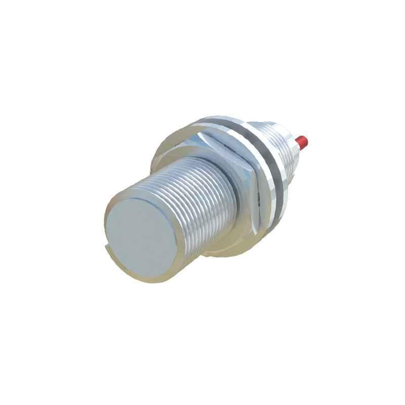
The BD2-S3 is defined by a set of precise technical parameters that dictate its application suitability. Typically, it features a standard sensing range, often up to 3mm for steel targets, though this can vary slightly based on the target material's properties and size. It is available in various housing styles, including tubular threaded barrels (e.g., M8, M12, M18, M30) with built-in LEDs for status indication. The sensor is designed for DC operation, commonly in a 3-wire configuration (PNP or NPN output, normally open or normally closed) with a wide operating voltage range, such as 10-30V DC. Key performance features include high switching frequency, enabling detection of rapidly moving objects, and excellent temperature stability, allowing operation in a broad ambient temperature range from -25°C to +70°C. Furthermore, it boasts high immunity to electrical noise and is often equipped with short-circuit and reverse polarity protection, safeguarding both the sensor and the connected control system from wiring errors or fault conditions.
Installation and Wiring Considerations
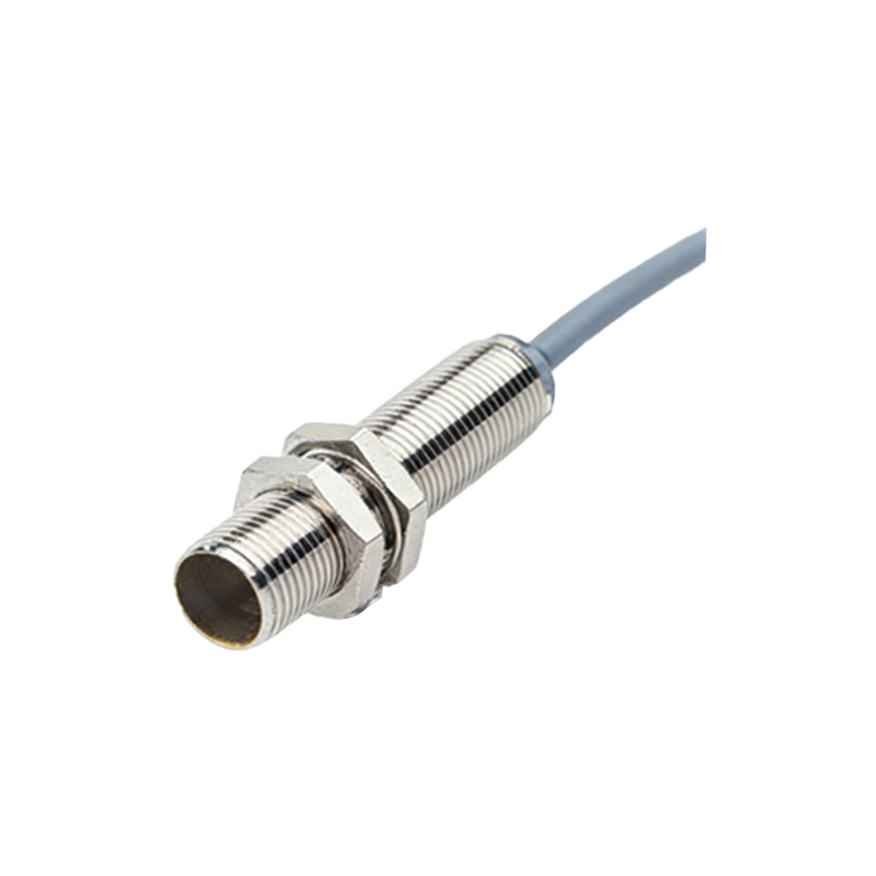
Proper installation is paramount for optimal performance and longevity of the BD2-S3 sensor. The sensor must be mounted securely, ensuring it is flush with or recessed in a metal mounting bracket if specified, to achieve its rated sensing distance. It is crucial to maintain the recommended lateral and axial clearance from other metal objects and adjacent sensors to prevent mutual interference, which can cause erratic switching behavior. For wiring, adherence to the manufacturer's diagram is essential. For a standard 3-wire DC sensor, the brown wire is typically connected to the positive supply voltage (+V), the blue wire to the common negative (0V), and the black wire is the switched output signal. The load (e.g., a PLC input, relay, or indicator) is connected between the black output wire and the positive or negative rail, depending on the PNP (sourcing) or NPN (sinking) output type. Always ensure power is disconnected during installation and use appropriate cable glands or connectors to maintain the sensor's IP67 or higher ingress protection rating, which guarantees resistance to dust and temporary immersion in water.
Application Scenarios and Best Practices
The versatility of the BD2-S3 makes it suitable for a vast array of industrial applications. Common uses include position verification of machine parts, such as detecting the presence of a cylinder in its end position, counting metallic products on a conveyor belt, and monitoring the open/closed status of doors or guards for safety interlocking. In robotic applications, it can be used for precise end-of-arm tooling detection or pallet presence sensing. A best practice is to select a sensor with a sensing distance approximately 1.5 times the required operational distance to account for mechanical tolerances and wear. Always use a target made of the same material specified in the datasheet (typically mild steel) for calibration. For non-ferrous metals like aluminum or copper, the effective sensing range will be reduced, and a correction factor must be applied. Regular maintenance involves cleaning the sensing face from accumulated debris, oil, or metal chips, and periodically checking the mounting integrity and cable condition.
Troubleshooting Common Issues
Even with a reliable sensor like the BD2-S3, issues can arise. A systematic approach to troubleshooting is recommended. If the sensor fails to detect a target, first verify the power supply voltage at the sensor terminals is within the specified range. Check the status LED; if it is off, there may be a power or wiring fault. If the LED is on but not switching, ensure the target is within the sensing range, is of sufficient size and material, and that there is no interfering metal in the vicinity. Erratic switching can often be traced to electrical noise;