Understanding Photoelectric Sensor Fundamentals
Photoelectric sensors are critical components in industrial automation, utilizing light beams to detect the presence, absence, or distance of objects. Their operation hinges on three primary components: an emitter (light source), a receiver, and supporting circuitry. Common types include through-beam, retro-reflective, and diffuse reflective sensors, each with distinct operational principles. Through-beam sensors feature separate emitter and receiver units, offering the longest sensing ranges and highest reliability. Retro-reflective models use a single housing with both emitter and receiver, relying on a reflector to bounce the light beam back. Diffuse sensors detect objects by measuring the light reflected directly from the target's surface. Understanding these fundamentals is the first step toward effective maintenance, as different types have unique vulnerabilities and care requirements. Proper identification of the sensor model and its operational mode is essential before performing any maintenance procedure.
Establishing a Routine Inspection Schedule
A proactive maintenance strategy begins with a consistent inspection schedule. For sensors in harsh or critical applications, visual inspections should be conducted weekly. In cleaner, less demanding environments, monthly checks may suffice. The inspection checklist must include verifying the physical condition of the sensor housing, lens, and mounting hardware. Look for cracks, dents, or signs of impact that could compromise the internal components or alignment. Check the integrity of the cable and connector strain relief; fraying or exposed wires can lead to signal loss or short circuits. Ensure the mounting brackets are secure, as vibration can loosen fasteners over time, causing misalignment. Document each inspection, noting any observations such as accumulated dirt, moisture ingress, or minor physical damage. This historical record helps predict failure patterns and plan preventative replacements.
Lens and Optical Surface Cleaning Procedures
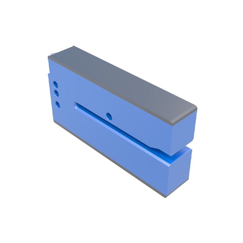
The optical lens is the most vulnerable part of a photoelectric sensor. Contaminants like dust, oil mist, coolant, or plastic shavings can adhere to the lens, attenuating the light beam and causing false triggers or detection failures. Cleaning must be performed with care to avoid scratching the optical surface. First, use dry, compressed air to blow away loose particulate matter. Hold the air nozzle at an angle to avoid driving debris into sensor seams. For stubborn residues, apply a small amount of isopropyl alcohol (90% or higher concentration) to a lint-free microfiber cloth or optical wipe. Gently wipe the lens in a circular motion from the center outward. Never spray liquid directly onto the sensor. For sensors with protective windows or air purge fittings, ensure these accessories are also clean and functional. After cleaning, perform a functional test to verify the sensor's detection capability has been restored.
Verifying Alignment and Sensing Stability
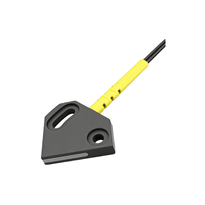
Misalignment is a leading cause of photoelectric sensor failure. Even slight shifts can break the beam path in through-beam or retro-reflective setups. After cleaning or any nearby machinery maintenance, realignment checks are mandatory. For through-beam sensors, use the receiver's alignment indicator (often an LED or signal strength meter) to maximize the received light intensity. Slowly adjust the sensor's position until the indicator shows peak performance. For retro-reflective sensors, ensure the reflector is clean and squarely aligned with the sensor face. Diffuse sensors require checking the background suppression setting if applicable, ensuring the sensing distance is correctly calibrated for the target object. Utilize the sensor's teach-in function or potentiometer to adjust sensitivity, avoiding settings that are too high (causing instability from background reflection) or too low (missing weak signals). Monitor the sensor's output on a control panel or PLC to confirm stable operation without chatter.
Electrical Connection and Signal Integrity Checks
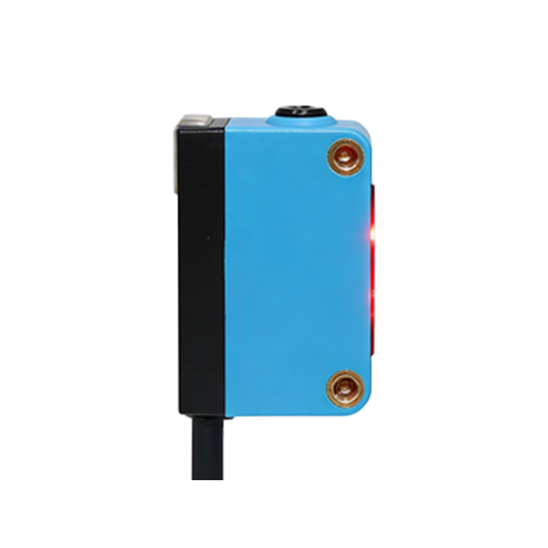
Electrical issues often manifest as intermittent operation. Regularly inspect the sensor's cable connections at both the sensor head and the interface module or controller. Look for corrosion on pins, especially in humid environments. Ensure connectors are fully seated and locked. Measure the supply voltage at the sensor terminals under load to confirm it is within the specified range (typically 10-30V DC). Voltage drops due to long cable runs or undersized wiring can cause unreliable operation. Use a multimeter or oscilloscope to check the output signal's behavior. A healthy switching output should show a clean transition between voltage levels. Noise or fluctuations on the output line can indicate internal component degradation or external electromagnetic interference. Consider installing shielded cables and proper grounding if noise is suspected. For networked or smart sensors, verify communication protocols and data integrity through the host system's diagnostic tools.
Environmental Protection and Hazard Mitigation
The operating environment dictates specific protective measures. Sensors exposed to washdown conditions require high IP (Ingress Protection) ratings (e.g., IP67, IP69K). Regularly inspect seals and gaskets for deterioration. In environments with airborne oils or coolants, sensors with stainless steel housings or chemical-resistant coatings are preferable. Extreme temperatures can affect performance; ensure the sensor's operating temperature range suits the application. Avoid mounting sensors near sources of intense ambient light (e.g., welding arcs, sunlight through windows), which can swamp the receiver. Use sensors with modulated LED light sources and synchronous detection circuits to reject ambient light interference. For high-vibration areas, employ vibration-damping mounts and secure cable management with conduit or cable carriers. Implementing these environmental controls extends sensor life and reduces false trips.
Diagnosing Common Failure Modes
Systematic troubleshooting saves time during downtime. If a sensor fails, first replicate the fault condition. Check for obvious physical damage, contamination, or loose connections. Use the sensor's built-in diagnostic LED as a primary clue: a steady LED may indicate power but no target detection, while a flashing LED often signals misalignment, weak signal, or a fault code. Swap the sensor with a known-good unit from a non-critical area to isolate the problem to the sensor itself or the external wiring/controller. For through-beam systems, try temporarily bypassing the reflector or realigning. Review the installation against the sensor's datasheet specifications, ensuring the target size, reflectivity, and sensing distance are within limits. Common failures include LED emitter degradation over time (reducing range), receiver contamination, and damaged internal circuitry from voltage spikes. Keeping a log of failures aids in identifying recurring issues.
Implementing Predictive Maintenance Strategies
Moving beyond reactive repairs, predictive maintenance leverages sensor data and trends. Many modern photoelectric sensors provide diagnostic information like signal strength, operating hours, or temperature via IO-Link or other industrial networks. Monitor the received light intensity trend; a gradual decline often precedes a failure, signaling lens fouling or emitter aging. Schedule cleaning or replacement when the intensity drops below a predefined threshold. Analyze mean time between failures (MTBF) data for specific sensor models in your application to optimize spare parts inventory. Consider installing redundant sensor setups in critical processes to allow for maintenance without production stoppages. Training maintenance personnel on these advanced techniques ensures they can interpret data and act before a catastrophic failure occurs, maximizing system uptime and return on investment.