Introduction to Photoelectric Sensor Wiring
Photoelectric sensors are fundamental components in industrial automation, playing a critical role in object detection, positioning, and counting. Their functionality relies on emitting a light beam and detecting changes in the received light. However, their integration into control systems is governed by their electrical wiring configuration. The terms "2-wire," "3-wire," and "4-wire" refer to the number of electrical connections required to power the sensor and transmit its output signal. Selecting the correct wiring system is paramount for ensuring reliable operation, system safety, and compatibility with Programmable Logic Controllers (PLCs) and other control devices. This article delves into the operational principles, advantages, disadvantages, and typical applications of each wiring configuration.
The 2-Wire Photoelectric Sensor
A 2-wire photoelectric sensor is the simplest in terms of connection. It is wired in series with the load, much like a conventional switch. The two wires handle both the power supply for the sensor's internal circuitry and the switching of the load current. When the sensor is active (e.g., detects an object), it closes an internal solid-state switch, allowing current to flow through itself to power its electronics and then onward to the load. A key characteristic is that a small leakage current, often called residual current, flows even when the sensor is in its "off" state. This current must be considered to avoid inadvertently activating sensitive loads.
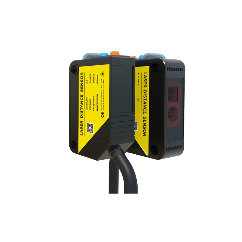
The primary advantage of the 2-wire sensor is its straightforward installation and space-saving design, as it requires fewer wires and terminals. It offers good protection against short circuits and is often used as a direct replacement for mechanical limit switches. The main drawbacks include a limited switching capacity, voltage drop across the sensor, and the potential for leakage current issues. They are commonly found in applications with simpler control logic, such as directly controlling contactors, relays, or PLC digital inputs with high enough impedance.
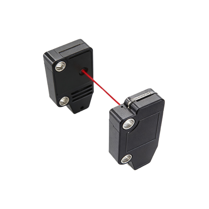
The 3-Wire Photoelectric Sensor
The 3-wire configuration is the most prevalent in modern industrial settings. It separates the power supply lines from the output signal line, offering superior performance and flexibility. The three wires are typically: Brown (or L+) for the positive power supply, Blue (or L- or N) for the common/negative power supply, and Black (or another color like white, gray) for the switched output signal. The sensor's internal electronics are powered continuously between the brown and blue wires. The black wire provides a discrete output that switches either to the positive supply voltage (for a PNP, sourcing output) or to the common/negative voltage (for an NPN, sinking output).
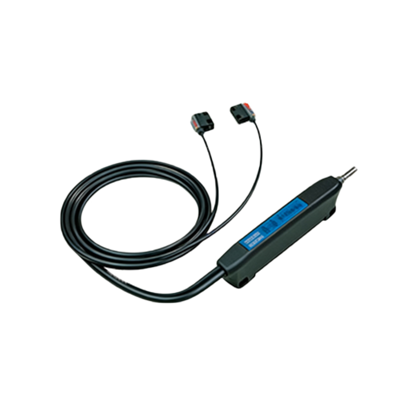
This separation eliminates the leakage current problem and minimizes voltage drop to the load. It allows for higher switching frequencies and lower power consumption by the sensor itself. The clear distinction between power and signal also simplifies troubleshooting. The choice between PNP and NPN is crucial and depends on the input type of the receiving controller (e.g., PLC). PNP (sourcing) is standard in many European and North American systems, while NPN (sinking) is common in some Asian markets. The 3-wire sensor is the versatile workhorse for most applications involving PLCs, counters, and sophisticated control systems.
The 4-Wire Photoelectric Sensor
A 4-wire photoelectric sensor builds upon the 3-wire design by providing two separate output channels. The wiring typically includes: Brown (+V), Blue (Common/0V), Black (Output 1), and White (Output 2). These dual outputs can be configured in several ways. A common configuration is one Normally Open (NO) and one Normally Closed (NC) output from the same sensing element, providing complementary signals. Another configuration is two independent NO outputs, which might be used for different functions or to send signals to two different devices.
This configuration offers enhanced control logic possibilities within a single sensor housing. For instance, the NO/NC setup can be used for fail-safe monitoring or to control two different states of a process without requiring an additional sensor or external relay logic. It increases functionality and can reduce wiring complexity in certain control panels by consolidating what would require two separate 3-wire sensors. The trade-off is a slightly larger sensor housing and a more complex initial setup. They are ideal for applications requiring redundant signals, safety interlocking, or multi-stage process control.
Key Selection Criteria and Comparison
Choosing the correct wiring system involves evaluating several factors. First, consider the *Control System Compatibility*: What type of input does your PLC or controller accept? This dictates the need for PNP vs. NPN in 3/4-wire sensors. Second, assess the *Electrical Load*: Check the sensor's maximum switching current and voltage against your load's requirements. 2-wire sensors have more limitations here. Third, factor in *Leakage Current*: For very sensitive loads or high-impedance PLC inputs, the residual current of a 2-wire sensor may be problematic. Fourth, consider *Installation and Maintenance*: 2-wire systems offer simpler wiring, while 3-wire systems offer easier diagnostics. Finally, evaluate *Functionality Needs*: Does the application require a simple on/off signal (2 or 3-wire) or complementary/dual signals (4-wire)?
In summary, 2-wire sensors offer simplicity for basic switching. 3-wire sensors provide reliable, high-performance integration with modern controllers and are the industry standard. 4-wire sensors deliver advanced functionality for more complex control tasks. Understanding the electrical and functional distinctions between these wiring schemes is essential for designing robust, efficient, and safe automated systems.