Understanding Photoelectric Sensor Fundamentals
Photoelectric sensors operate by emitting a light beam—typically infrared, visible red, or laser—and detecting changes in the received light intensity. The core principle involves a transmitter (light source) and a receiver (photodetector). When an object interrupts or reflects this beam, the sensor's output state changes, triggering a signal. Common types include through-beam (opposed), retro-reflective, and diffuse (proximity) sensors. Each type has distinct measurement considerations. Through-beam sensors offer the longest sensing range and highest reliability, as the receiver directly detects the transmitter's beam. Retro-reflective sensors use a reflector to bounce light back to the receiver, while diffuse sensors rely on light reflecting directly off the target object. Understanding these fundamentals is critical before attempting any measurement, as the methodology varies significantly between configurations.
Essential Tools and Equipment for Measurement
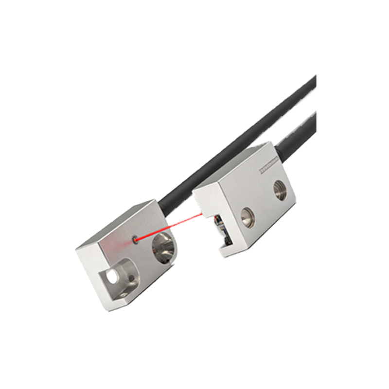
Accurate measurement of photoelectric sensor values requires specific tools. A digital multimeter (DMM) is indispensable for checking voltage and current outputs. An oscilloscope is highly recommended for analyzing dynamic response, signal integrity, and timing characteristics, especially for pulsed or modulated light systems. For precise optical evaluation, a lux meter or a specialized photoelectric sensor tester can measure received light intensity. Additionally, you will need a stable DC power supply matching the sensor's voltage rating (e.g., 10-30 VDC), calibrated test targets (with specified reflectivity and size), and appropriate cabling. Always refer to the sensor's datasheet for exact specifications regarding load conditions, wiring diagrams, and output types (NPN/PNP, analog, or digital).
Measuring Digital (Switch) Output Sensors
Most photoelectric sensors provide a digital (on/off) output. To measure this, first ensure correct power connection. Using a multimeter set to DC voltage, probe the output wire (typically black or brown) and the common/ground wire (typically blue). Without a target, note the voltage; it should be near supply voltage (for a PNP sourcing output) or near 0V (for an NPN sinking output). Introduce a valid target within the sensing range. The output voltage should switch states. For example, a PNP sensor's output may switch from ~24V to ~0V when activated. Verify the switching differential—the distance or condition difference between the "on" and "off" points. This hysteresis prevents output chatter. Also, measure response time by triggering the sensor and observing the output transition on an oscilloscope, ensuring it meets the required speed for the application.
Measuring Analog Output Sensors
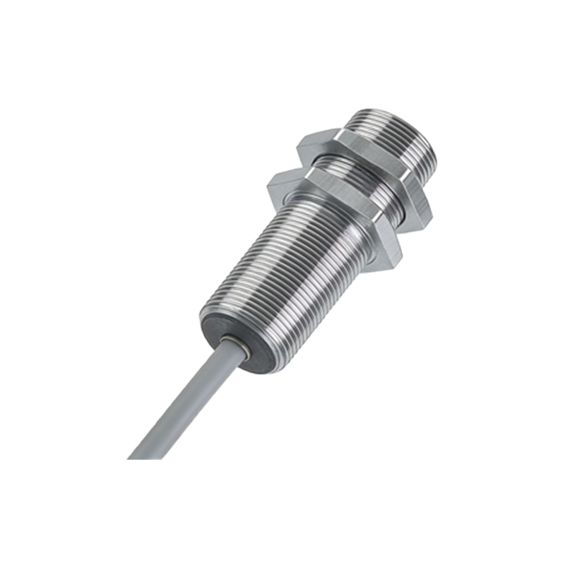
Analog output sensors provide a continuous signal (e.g., 0-10V or 4-20mA) proportional to the distance or reflectivity of the target. To measure, connect the sensor to power and link the analog output to a multimeter set to the appropriate mode (voltage or current). Position a target at a known reference distance. Record the output value. Gradually move the target through the sensing range, noting the output change. The relationship should be linear (or as specified) across the range. Check for saturation—points where the output no longer changes despite target movement. It is also vital to measure the resolution and repeatability. Perform several measurements at the same position to ensure consistent output. Any significant drift or noise observed on an oscilloscope may indicate electrical interference or sensor instability.
Evaluating Light Intensity and Alignment
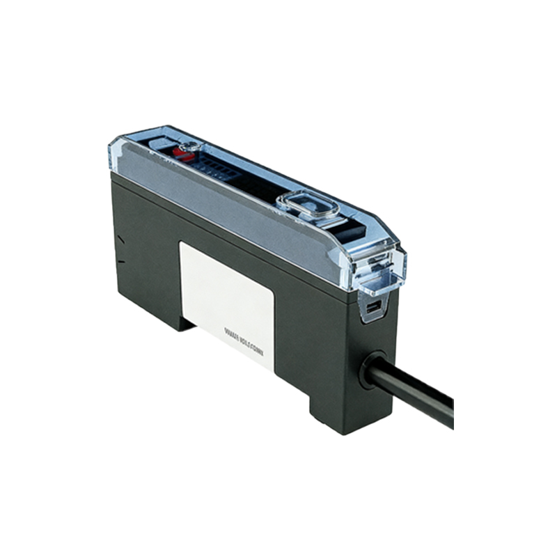
The received light intensity is a key health indicator. Many sensors have a stability or signal strength indicator (LED). For precise measurement, use a photoelectric tester or a lux meter positioned at the receiver. For through-beam and retro-reflective types, measure intensity with and without the target interruption. A significant drop (often 70-100%) should occur when blocked. For diffuse sensors, measure intensity with the target at the standard sensing distance. Compare readings to the datasheet's minimum detectable intensity. Alignment is critical for through-beam and retro-reflective sensors. Use the sensor's alignment aid (if available) or carefully adjust until the received light intensity is maximized. Even slight misalignment can cause unreliable operation, especially over long distances or in vibrating environments.
Troubleshooting Common Measurement Issues
Inconsistent readings often stem from environmental factors. Ambient light interference can be identified by powering off the sensor's transmitter (if possible) and measuring the receiver's output. Use sensors with modulated light to mitigate this. Electrical noise may corrupt analog signals; ensure proper shielding and grounding. If the sensor does not switch, verify the load compatibility and current draw. Overloading the output can cause failure. For false triggers, check for reflective surfaces or small particles in the sensing path. Additionally, verify that the target's size, color, and material are within specifications. Dark, matte, or transparent objects may not reflect sufficient light for diffuse sensors. Always perform measurements under actual operating conditions when possible, as temperature and humidity can affect performance.
Implementing Best Practices for Reliable Operation
To ensure long-term accuracy, establish a regular calibration and verification schedule. Document baseline measurements for light intensity and output values under standard test conditions. When installing multiple sensors, prevent optical crosstalk by ensuring sufficient spacing or using sensors with different modulation frequencies. For analog sensors, implement filtering in the control system to smooth noise. Always respect the sensor's rated sensing distance—operating at the limit reduces margin for error. Finally, keep optical surfaces clean from dust, oil, and condensation, as contamination drastically reduces light transmission. By following these systematic measurement and maintenance procedures, engineers can guarantee optimal sensor performance and system reliability in industrial automation applications.