Proximity sensor switches are essential components in modern automation and control systems. They detect the presence or absence of an object without physical contact, making them ideal for harsh environments where reliability is critical. This article provides a detailed explanation of proximity sensor switch diagrams, helping you understand their operation, wiring, and applications.
A typical proximity sensor switch diagram consists of several key parts: the sensor head, oscillator, trigger circuit, output stage, and power supply. The sensor head generates an electromagnetic field. When a metal object enters this field, eddy currents are induced, causing a change in the oscillator's amplitude. This change is detected by the trigger circuit, which then activates the output stage—usually a transistor or relay—to switch an external load. Diagrams often use symbols to represent these components, such as a coil for the oscillator and a switch for the output.
Wiring diagrams are crucial for correct installation. Most proximity sensors have three or four wires: brown for positive voltage, blue for negative or ground, black for output signal, and sometimes white for a second output or function. In a standard NPN wiring diagram, the black wire connects to the load, which is then linked to the positive supply. For PNP types, the black wire connects to the load, which ties to ground. Diagrams also show protective elements like fuses or surge suppressors to prevent damage from voltage spikes. Always refer to the manufacturer's diagram, as colors and configurations can vary.
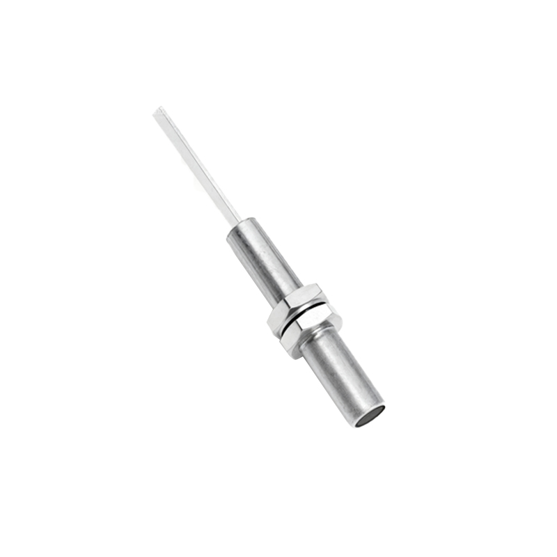
Understanding the diagram helps in troubleshooting. If a sensor fails, check the power supply lines first using a multimeter. Ensure the object is within the sensing range and made of compatible material—inductive sensors work only with metals, while capacitive sensors detect both metals and non-metals. The output indicator LED, often shown in diagrams, can signal normal operation or faults. For instance, a constantly lit LED might indicate a short circuit, while no light could mean power issues.
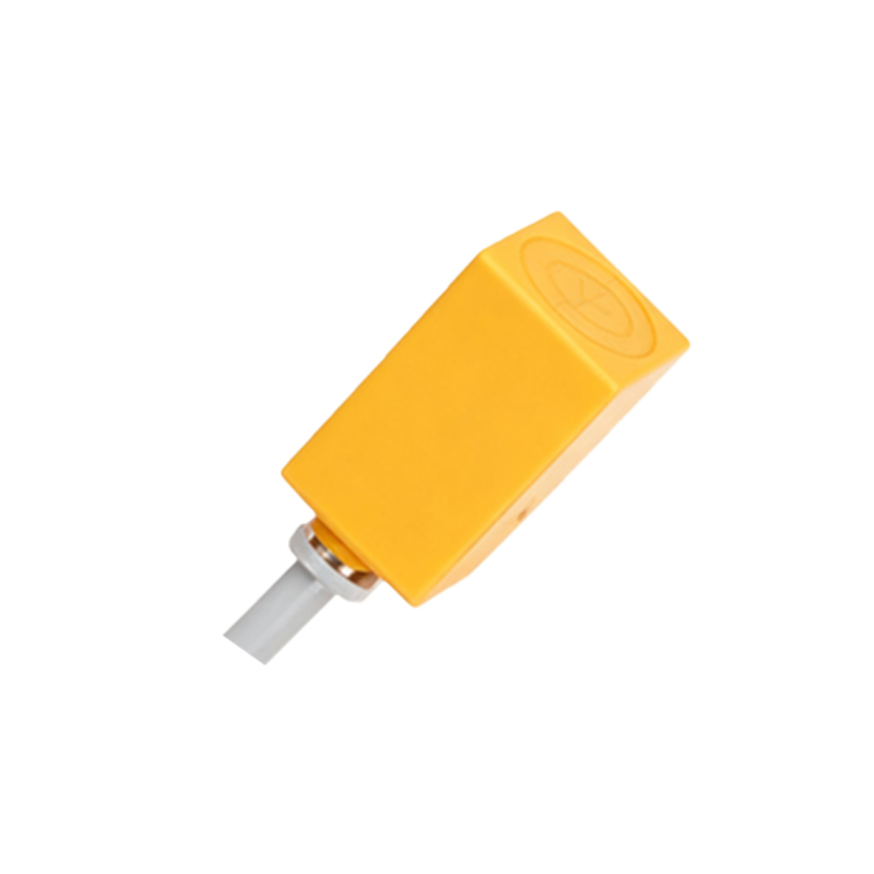
Proximity sensor switches are used in diverse industries. In automotive assembly, they detect parts on conveyor belts. In packaging, they count products or monitor fill levels. Diagrams for these applications include additional components like timers or counters, connected via the sensor's output. For safety systems, such as machine guarding, diagrams illustrate how sensors interlock with control relays to halt machinery when an object is detected.
When selecting a sensor, consider the diagram's specifications: sensing distance, response time, and output type. For example, a 12mm inductive sensor might have a sensing distance of 4mm and a response time of 1ms. Diagrams often note these details alongside wiring instructions. Environmental factors like temperature or humidity can affect performance, so some diagrams include ratings for IP67 protection against dust and water.
In summary, proximity sensor switch diagrams are vital tools for installation, operation, and maintenance. They translate complex electronic functions into visual guides, ensuring systems run efficiently. By mastering these diagrams, technicians can optimize automation processes, reduce downtime, and enhance safety. Always consult the latest diagrams from reputable sources, as technology evolves with improved designs and features.