Understanding Metal Proximity Sensor Fundamentals
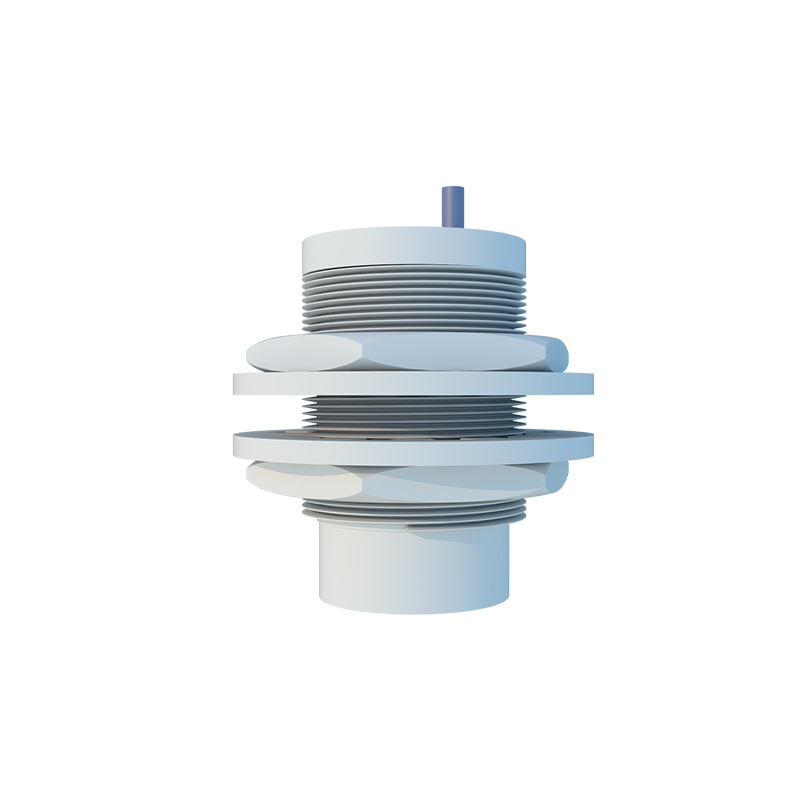
Metal proximity sensors are indispensable components in modern industrial automation, providing non-contact detection of metallic objects. These sensors operate primarily on two principles: inductive and magnetic. Inductive sensors generate an electromagnetic field and detect changes caused by a metallic target entering this field. Magnetic sensors, often reed switches or Hall-effect sensors, react to the presence of a magnetic field or ferrous metal. Understanding the specific type—whether it's a shielded (flush-mountable) or unshielded (non-flush) inductive sensor, or a magnetic proximity switch—is the critical first step before any testing procedure. This foundational knowledge dictates the appropriate testing methodology and expected behavior.
Essential Pre-Testing Preparations and Safety
Prior to initiating any tests, comprehensive preparation is mandatory to ensure safety and accuracy. Begin by consulting the sensor's datasheet for its specifications, including nominal sensing distance (Sn), operating voltage, output type (PNP/NPN, NO/NC), and housing material. De-energize the electrical circuit completely. Implement lockout-tagout (LOTO) procedures to prevent accidental re-energization. Visually inspect the sensor for any physical damage, corrosion, or loose wiring. Verify that the sensor is correctly installed with proper alignment and that the target material (e.g., mild steel, stainless steel, aluminum) and size meet the manufacturer's specifications, as these factors significantly influence sensing performance.
Step-by-Step Functional Testing Procedure
A systematic functional test is the core of evaluating sensor health. First, reconnect power to the circuit. Using a multimeter set to the appropriate DC voltage range, measure the supply voltage at the sensor's terminals to confirm it is within the specified range. For a 3-wire DC sensor, identify the brown (typically +V), blue (typically 0V), and black (typically output) wires. With no target present, measure the voltage between the output wire (black) and the blue wire (0V). For a normally open (NO) sensor, this should read near 0V (or supply voltage for a NPN type). Then, introduce a standard target—a piece of mild steel of the specified thickness—slowly towards the active face of the sensor. Observe the exact point where the sensor activates. The multimeter reading should switch (e.g., from 0V to ~24V for a PNP NO sensor). The activation distance should be within 90-110% of the rated sensing distance (Sn).
Evaluating Performance and Hysteresis
Beyond simple on/off functionality, performance characteristics like hysteresis and repeatability define sensor quality. Hysteresis is the difference between the switch-on point (as the target approaches) and the switch-off point (as the target recedes). To measure this, mark the position where the sensor activates as you move the target forward. Then, slowly retract the target and mark the position where it deactivates. The distance between these two points is the hysteresis. A sufficient hysteresis (typically 3-15% of Sn) prevents output oscillation when a target is at the sensing edge. Next, test repeatability by performing the activation test multiple times. The variation in the switch-on point should be minimal, often less than 5% of Sn, indicating stable and reliable operation.
Troubleshooting Common Sensor Failures
If the sensor fails the functional test, methodical troubleshooting is required. If there is no output change, double-check wiring against the datasheet diagram. Incorrect connection of PNP vs. NPN to the controller is a common error. Use the multimeter to check for a short or open circuit in the sensor's output. If the sensing distance is drastically reduced, potential causes include sensor misalignment, accumulation of metallic debris on the active face, degradation of the internal oscillator circuit, or an incorrect target material (e.g., aluminum has a much shorter sensing range than steel for standard inductive sensors). Environmental factors like extreme temperatures, strong electromagnetic interference, or exposure to corrosive chemicals can also lead to premature failure or erratic behavior.
Advanced Diagnostics and Maintenance Tips
For persistent or intermittent issues, advanced diagnostics may be necessary. An oscilloscope can be used to examine the quality and stability of the sensor's output signal, checking for noise or slow switching times. Monitoring the current draw of the sensor can also reveal internal faults. Proactive maintenance is key to longevity. Establish a regular calibration and inspection schedule. Keep the sensor face clean from contaminants like oil, dust, or metal chips. Ensure the mounting hardware is secure to prevent vibration-induced damage. For critical applications, consider implementing redundancy or using sensors with diagnostic LED indicators or IO-Link capability