Understanding the R11 Proximity Sensor
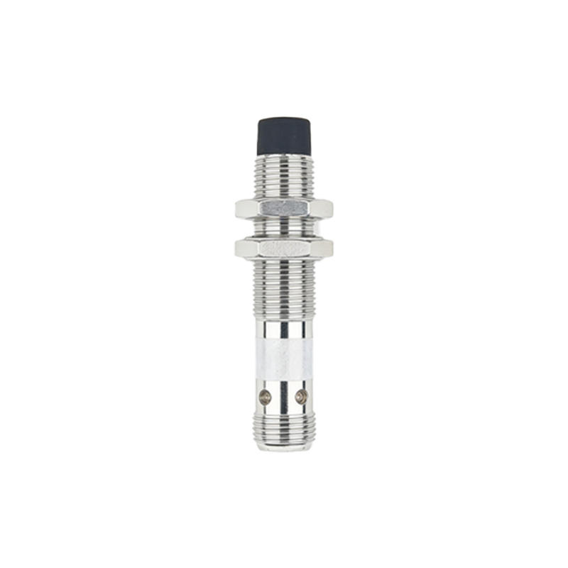
The R11 series represents a robust line of inductive proximity sensors widely utilized in industrial automation for non-contact detection of metallic objects. These sensors operate on the principle of electromagnetic induction, where an oscillator generates a high-frequency electromagnetic field from the sensing face. When a metallic target enters this field, eddy currents are induced, causing a change in the oscillator's amplitude. This change is detected by the sensor's circuitry, triggering a switching output. The R11 is prized for its durability, resistance to environmental factors like dust and moisture, and its consistent performance in demanding applications such as conveyor systems, machine tools, and robotic assembly lines. Proper calibration is not merely a recommendation but a critical procedure to ensure the sensor operates within its specified sensing range, provides reliable object detection, and minimizes false triggers that could lead to production downtime or safety incidents.
Pre-Calibration Preparation and Safety
Before initiating any calibration procedure, a thorough preparatory phase is essential. First, ensure the system power is completely locked out and tagged out (LOTO) to prevent accidental energization. Verify the sensor's model number and consult the manufacturer's datasheet for specific technical parameters, including nominal sensing distance (Sn), operating voltage range, output type (PNP/NPN, NO/NC), and the recommended target material and size. Gather the necessary tools: a set of precision feeler gauges or calibration targets made of the correct material (typically mild steel), a digital multimeter, and the appropriate screwdrivers. Inspect the R11 sensor physically for any signs of damage, corrosion, or debris accumulation on the sensing face. Clean the face meticulously with a soft, dry cloth. Ensure the sensor is correctly mounted, as misalignment can severely affect performance. Document the initial settings and the application's normal operating conditions as a baseline.
Calibration Procedure: Step-by-Step Instructions
Begin by applying power to the circuit. Using the digital multimeter, monitor the output signal of the sensor. For a normally open (NO) configuration, the output should be low (or off) when no target is present. Introduce the standard calibration target—a square plate of 1mm thick mild steel with sides equal to the sensor's sensing face diameter or as specified. Slowly move the target axially towards the sensing face. Observe the point at which the output switches state (e.g., from OFF to ON for NO). This distance is the actual sensing point. Compare this to the rated operating distance (often 0.8 x Sn). Most R11 sensors have a potentiometer or a teach-in function for adjustment. Locate the calibration potentiometer, typically a small screw recessed in the housing. With the target positioned at the desired operational distance, carefully adjust the potentiometer until the output switches precisely at that point. Make minute adjustments and allow the sensor to stabilize after each turn. For models with teach-in, follow the specific sequence (often involving power cycling with a button press) to set the switch point automatically.
Verification and Functional Testing
After adjustment, verification is crucial to confirm calibration accuracy and repeatability. Remove the target and confirm the output returns to its normal state. Approach the target to the sensor at the calibrated distance multiple times, noting the consistency of the switch point. Test with the actual target material used in the application, if different from the calibration standard, as different metals (steel, aluminum, brass) have different correction factors. Perform tests at the extremes of the operating voltage range to ensure stable performance. Check for hysteresis, which is the difference between the switch-on and switch-off points; a small, consistent hysteresis is normal. It is also advisable to test for potential interference from adjacent metallic structures or other sensors, which might require slight recalibration of the sensing distance to avoid mutual interference. Document all final settings, measured distances, and test results for future reference and maintenance logs.
Troubleshooting Common Calibration Issues
Several issues may arise during or after calibration. If the sensor fails to trigger, verify power supply polarity and voltage, check wiring connections, and confirm the output load is within specifications. An unstable or chattering output often indicates an incorrectly set sensitivity (too high), electrical noise interference, or an unsuitable target material. Ensure proper grounding and shielding of cables. If the sensing range is significantly shorter than specified, the sensor may be damaged, the sensing face may be dirty, or the target material may have a low correction factor (like aluminum). For sensors that cannot be adjusted to the required point, internal component failure is a possibility. Always cross-reference observed behavior with the diagnostic indicators, if available, on the sensor itself. Persistent issues typically warrant sensor replacement.