Introduction to PS400S Photoelectric Sensor
The PS400S photoelectric sensor is a versatile and reliable component widely used in industrial automation for object detection, counting, and positioning. Its robust design ensures stable performance in harsh environments, including areas with dust, moisture, or vibration. Understanding the correct wiring diagram is crucial for safe installation and optimal functionality. This guide provides a detailed overview of the PS400S wiring configuration, helping engineers and technicians integrate it seamlessly into control systems. Proper wiring not only prevents operational failures but also extends the sensor's lifespan, making it a cost-effective solution for production lines and machinery.
Key Components and Pin Configuration
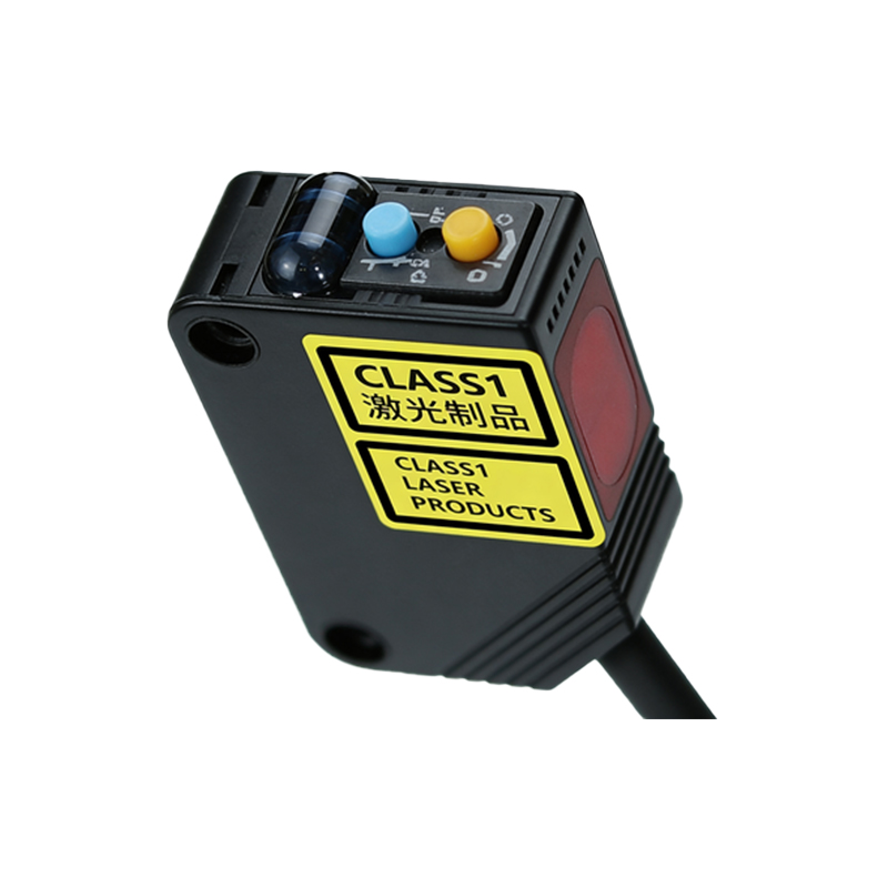
The PS400S sensor typically features a compact housing with a built-in amplifier and multiple connection pins. Common models include three or four wires, corresponding to power supply, output, and ground connections. For a standard three-wire DC sensor, the pins are labeled as follows: Brown wire (or pin 1) for positive voltage supply (+V), Blue wire (or pin 2) for negative or ground (0V), and Black wire (or pin 3) for the output signal. Some variants may include a white wire for complementary output or diagnostic functions. It is essential to refer to the manufacturer's datasheet for specific models, as pin assignments can vary based on output type (e.g., NPN or PNP) and sensing mode (e.g., retro-reflective or through-beam).
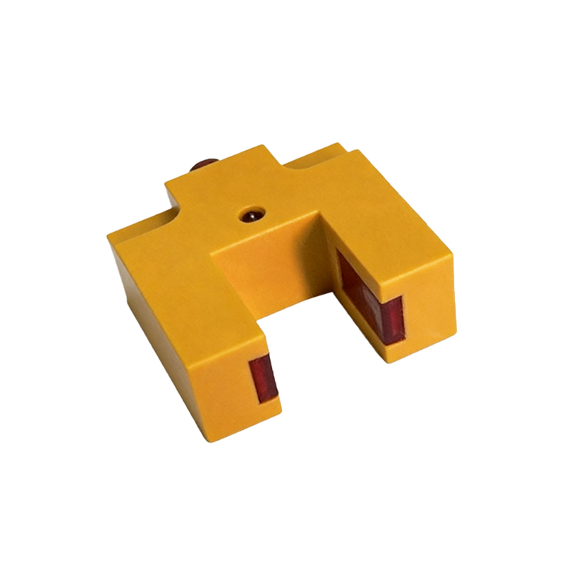
Wiring Diagram for NPN Output Type
For PS400S sensors with NPN output, the wiring connects to a sinking input circuit. Connect the brown wire to the positive DC supply voltage, typically ranging from 10 to 30 VDC. The blue wire attaches to the common ground (0V). The black output wire links to the load, such as a programmable logic controller (PLC) input or relay, which must be connected to the positive supply through an internal or external resistor. When the sensor detects an object, the NPN transistor switches, allowing current to flow from the load to ground, creating a low signal. Ensure proper insulation and use shielded cables in electrically noisy environments to prevent interference with signal accuracy.
Wiring Diagram for PNP Output Type
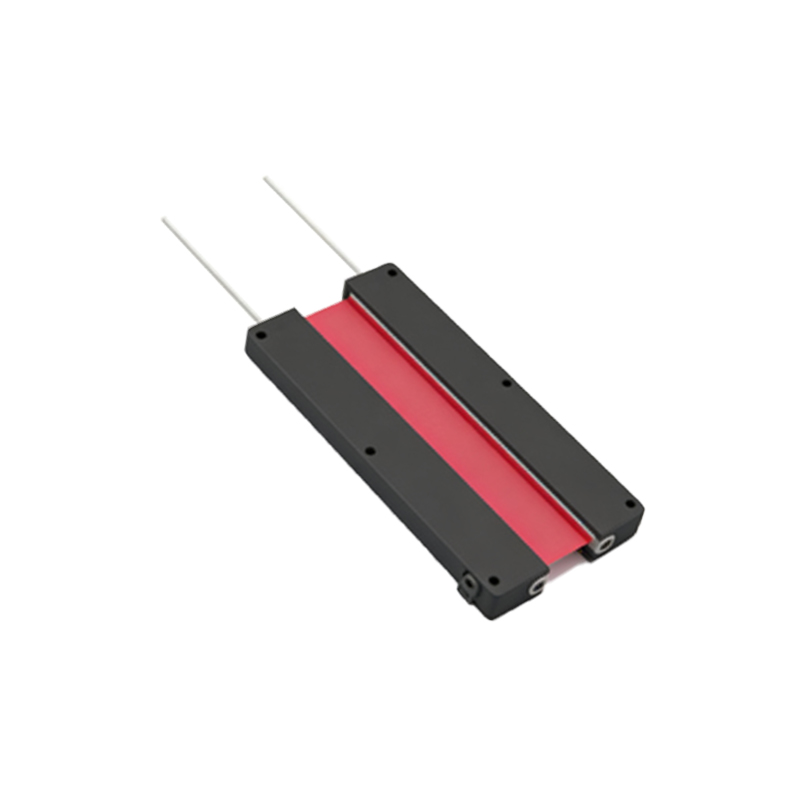
In PNP output configurations, the PS400S sensor sources current to the load. Wire the brown lead to the positive DC supply and the blue lead to ground. The black output wire connects directly to the load, which is then linked to ground. Upon detection, the PNP transistor activates, sending a high signal from the sensor to the load. This setup is common in European systems and compatible with sourcing PLC inputs. Always verify voltage ratings to avoid damage—exceeding 30 VDC can harm internal circuits. For added safety, incorporate a fuse or circuit breaker in the power line to protect against short circuits or overloads.
Power Supply and Grounding Considerations
A stable power supply is vital for PS400S operation. Use a regulated DC source within the specified range (e.g., 12-24 VDC) to ensure consistent performance. Avoid sharing power lines with high-current devices like motors, as voltage drops or spikes can cause false triggers or sensor resets. Grounding the sensor properly reduces electromagnetic interference (EMI). Connect the blue wire to a clean, dedicated ground point, and if using metal housings, bond them to earth ground for shielding. In multi-sensor installations, employ a common ground bus to minimize potential differences and enhance system reliability.
Output Load and Connection to Control Systems
The PS400S output can drive various loads, including PLCs, relays, or indicator lights. Check the maximum load current (usually up to 100 mA) to prevent overheating. For PLC interfaces, match the sensor's output type (NPN/PNP) with the input module specifications. Use twisted-pair cables for long runs to reduce noise, and keep cable lengths under 100 meters to maintain signal integrity. If connecting to relays, add a flyback diode across the coil to suppress voltage spikes. Test the connection with a multimeter or oscilloscope to verify signal stability before full-scale deployment.
Troubleshooting Common Wiring Issues
Incorrect wiring often leads to sensor malfunctions. If the PS400S fails to detect objects, confirm power polarity—reversed connections can damage the unit. Check for loose wires or corrosion at terminals, and ensure voltage levels meet requirements. Intermittent signals may stem from EMI; relocate cables away from power lines or use ferrite cores. For persistent issues, consult the indicator LED: a steady light suggests proper power, while blinking indicates alignment or sensitivity problems. Always disconnect power before adjusting wiring to prevent electrical hazards.
Best Practices for Installation and Maintenance
Follow industry standards for installing PS400S sensors. Mount them securely on stable surfaces, aligning emitter and receiver precisely for accurate sensing. Maintain a clean lens free of debris, and periodically inspect wiring for wear or damage. Document wiring diagrams in system manuals for future reference. Train personnel on safe handling procedures, emphasizing lockout/tagout during maintenance. By adhering to these guidelines, users can maximize efficiency and reduce downtime in automated processes.