Understanding Proximity Sensor Function in Front Cover Systems
Proximity sensors installed on machinery front covers serve a critical safety and operational function. These non-contact sensors, typically inductive or capacitive types, detect the presence or absence of the metal front cover itself. Their primary role is to ensure the cover is securely closed before allowing the machine to initiate a potentially hazardous cycle. This interlock prevents accidental access to moving parts, electrical components, or high-pressure zones, thereby protecting personnel and equipment. The sensor generates a discrete signal—often a 24VDC on/off output—that is fed directly into the machine's programmable logic controller (PLC) or safety relay module. A correct "cover closed" signal is a prerequisite for the main drive or process to be enabled. Failure of this sensor can lead to unexpected machine downtime, production halts, or, in worst-case scenarios, compromise safety systems.
Common Symptoms of a Failing Front Cover Proximity Sensor
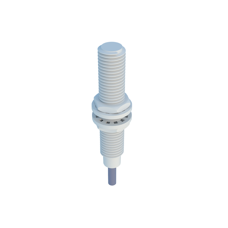
Identifying a faulty proximity sensor early is key to preventing major disruptions. Operators and maintenance technicians should be alert to several telltale signs. The most frequent symptom is intermittent machine stoppage or refusal to start, accompanied by a "Cover Not Closed" or similar error message on the Human-Machine Interface (HMI). The machine may cycle erratically, starting and stopping without operator intervention, indicating an unstable sensor signal. In some cases, the sensor might fail in a "safe" state, constantly indicating the cover is open even when it is firmly shut, rendering the machine inoperable. Conversely, a more dangerous failure mode is the sensor failing "live," where it continuously signals the cover is closed regardless of its actual position, bypassing the safety interlock. Physical indicators can include a missing or dimmed LED status light on the sensor body, or visible damage to the sensor face or cabling.
Step-by-Step Diagnostic and Troubleshooting Procedure
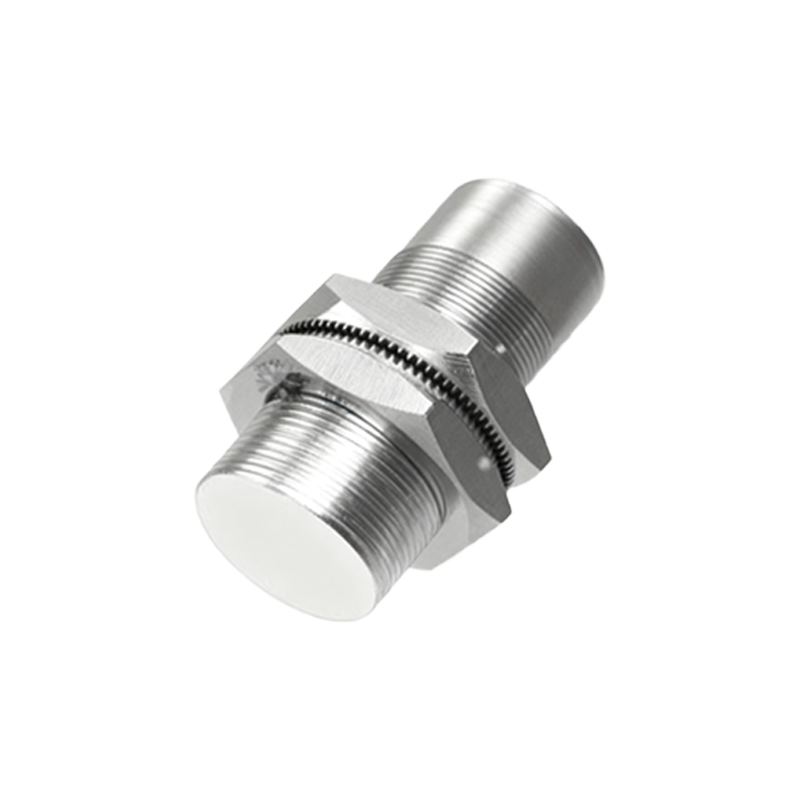
A systematic approach is essential for accurate diagnosis. First, always adhere to Lockout-Tagout (LOTO) procedures to ensure the machine is in a zero-energy state before any physical inspection. Begin with a visual check of the sensor, its mounting bracket, and the target area on the front cover. Look for accumulation of metal chips, dirt, or coolant that could interfere with sensing. Verify the sensor is properly aligned with the target; even a small misalignment can cause detection failure. Check the mounting hardware for tightness and inspect the cable for cuts, pinch points, or damaged connectors. After the visual inspection and with LOTO still applied, use a digital multimeter to perform continuity checks on the sensor's wiring back to the PLC input card. Next, power the system and use the multimeter to measure the voltage at the sensor's output. Compare the switching behavior (voltage high/low) as the cover is opened and closed against the sensor's datasheet specifications.
Potential Root Causes and Corrective Actions
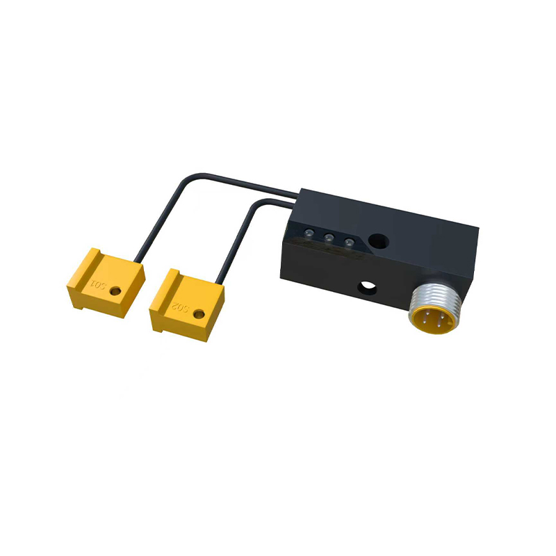
Diagnostics often point to one of several common root causes. Environmental contamination is a primary culprit; metallic dust adhering to an inductive sensor's face can saturate its field, while oil or coolant can bridge the gap for capacitive sensors. The corrective action is a thorough cleaning with appropriate solvents and implementing preventative measures like installing a protective boot. Mechanical misalignment or loosening of the sensor or its target due to vibration is another frequent issue. Realign the sensor to the specified gap (e.g., 1-2mm for many inductive sensors) and secure it with thread-locking compound if necessary. Electrical failures include damaged wiring, faulty connectors, or internal component failure within the sensor. Replace damaged cables and connectors. If the sensor itself is faulty, replacement is required. Ensure the replacement sensor has identical specifications: sensing type (PNP/NPN), output type (NO/NC), voltage rating, and physical size.
Preventive Maintenance Strategies for Sensor Longevity
Proactive maintenance significantly reduces unplanned downtime related to sensor faults. Establish a regular inspection schedule as part of the overall preventive maintenance (PM) program. This schedule should include visual inspections for cleanliness, alignment, and physical damage. Periodically verify the sensor's function and switching point using a non-ferrous or specified target during a planned machine stop. For harsh environments, consider upgrading to sensors with higher Ingress Protection (IP) ratings, such as IP67 or IP69K, which offer superior resistance to dust and washdowns. Using sensors with built-in diagnostics, like IO-Link variants, can provide detailed health status and operational parameters directly to the control system, enabling predictive maintenance. Finally, ensure all personnel are trained on the importance of the safety interlock system and avoid the dangerous practice of manually bypassing or "jumping out"