Introduction to Proximity Switches in Engraving Machines
Proximity switch sensors are essential components in modern engraving machines, providing non-contact detection of metallic objects to ensure precise positioning and safety. These sensors operate by generating an electromagnetic field, which detects the presence of a target without physical contact, reducing wear and tear. In engraving applications, they are commonly used to limit axis movement, detect tool presence, or trigger automated sequences. Understanding their wiring is crucial for proper installation, maintenance, and troubleshooting in industrial settings. This article details the wiring diagram for typical inductive proximity sensors, focusing on common configurations like 3-wire DC models, which are widely used in engraving equipment due to their reliability and ease of integration.
Types of Proximity Sensors and Their Specifications
Engraving machines primarily utilize inductive proximity sensors, designed to detect ferrous metals like steel or iron. Key specifications include sensing distance (e.g., 2mm to 15mm), output type (NPN or PNP), and voltage rating (typically 10-30V DC). NPN sensors, also known as sinking outputs, switch the negative side of the load, while PNP sensors (sourcing outputs) switch the positive side. The choice depends on the control system; for instance, many CNC controllers in engraving machines prefer PNP for compatibility with PLC inputs. Additionally, sensors may feature normally open (NO) or normally closed (NC) contacts, affecting circuit behavior when a target is detected. Always refer to the manufacturer's datasheet for exact ratings to prevent damage.
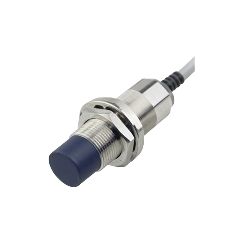
Wiring Diagram Components and Connections
A standard 3-wire DC proximity switch includes three leads: brown (positive), blue (negative), and black (output). For a PNP sensor, connect the brown wire to the positive DC supply (e.g., +24V), the blue wire to the negative or ground, and the black wire to the load (such as a PLC input or relay). The load is then linked to the negative supply to complete the circuit. In an NPN setup, the brown wire still connects to positive, blue to negative, but the black wire attaches to the load, which is tied to positive. Ensure proper shielding and routing of wires away from power cables to avoid electromagnetic interference, which can cause false triggers in sensitive engraving operations. Use twisted-pair cables for longer runs to enhance signal integrity.
Step-by-Step Wiring Installation Process
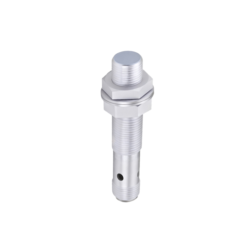
Begin by disconnecting power to the engraving machine to prevent electrical hazards. Mount the sensor securely on the machine frame, aligning it with the target area (e.g., near the spindle or axis limit). Strip the wire ends and connect them according to the diagram: for a PNP sensor, join brown to +V, blue to 0V, and black to the input terminal of the controller. Verify connections with a multimeter for continuity and correct voltage. After wiring, power on the system and test by moving a metal object near the sensor; the output LED should illuminate, and the controller should register the signal. Adjust the sensor position if needed to achieve optimal sensing range without false detections from nearby components.
Common Troubleshooting and Safety Tips
If the sensor fails to operate, check for loose connections, incorrect polarity, or insufficient voltage supply. Use a multimeter to measure voltage between brown and blue wires (should be within 10-30V DC) and output voltage on the black wire when activated. Ensure the target material is compatible; non-metallic objects won't trigger inductive sensors. Avoid installing sensors in areas with high temperatures or coolant splashes, as this can reduce lifespan. Regularly inspect wiring for damage and clean the sensor face to maintain accuracy. Always follow lockout-tagout procedures during maintenance to safeguard against accidental machine startup in engraving environments.

Integration with CNC Control Systems
In engraving machines, proximity sensors interface with CNC controllers to enable functions like homing, tool change detection, or emergency stops. Wire the sensor output to a digital input on the controller, configuring the software to recognize the signal as a limit switch or input trigger. For example, in Mach3 or GRBL-based systems, set the input pin in the configuration settings to activate when the sensor detects metal. Use opto-isolators or relays if voltage levels differ between the sensor and controller to prevent damage. Proper integration ensures smooth operation, reducing errors in intricate engraving tasks and enhancing overall machine productivity.
Conclusion and Best Practices
Correct wiring of proximity switch sensors is vital for the reliability and safety of engraving machines. Always select sensors matching the machine's electrical