Understanding Proximity Sensor Calibration Fundamentals
Proximity sensor calibration is a critical procedure that establishes the relationship between the sensor's output signal and the actual distance to a target object. This process ensures the sensor operates within its specified accuracy and repeatability parameters. All proximity sensors, whether inductive, capacitive, ultrasonic, or photoelectric, require proper calibration to perform reliably in industrial applications. The core principle involves adjusting the sensor's internal parameters so that its detection threshold, switching point, or analog output corresponds precisely to a predefined physical distance. Without accurate calibration, sensors may trigger too early or too late, leading to process errors, machine downtime, or product quality issues. The calibration process typically references a known standard, such as a precision gauge block or a calibrated distance tool, to set the sensor's response at one or more specific points in its measurement range.
Essential Tools and Equipment for Precise Calibration
Successful calibration demands the right tools. The primary equipment includes a set of certified calibration targets. For inductive sensors, these are typically ferrous and non-ferrous metal plates of specified thickness and material grade. Capacitive sensors require dielectric material targets. A high-precision positioning stage or micrometer stand is indispensable for moving the target toward and away from the sensor face with micron-level accuracy. A reliable multimeter or oscilloscope is needed to monitor the sensor's output signal—be it a digital switch (PNP/NPN) state change or an analog voltage/current shift. For programmable sensors, a configuration tool or software interface is necessary to adjust parameters. The working environment must be stable, free from excessive vibration, temperature fluctuations, and electromagnetic interference that could skew results.
Step-by-Step Calibration Procedure for Common Sensor Types
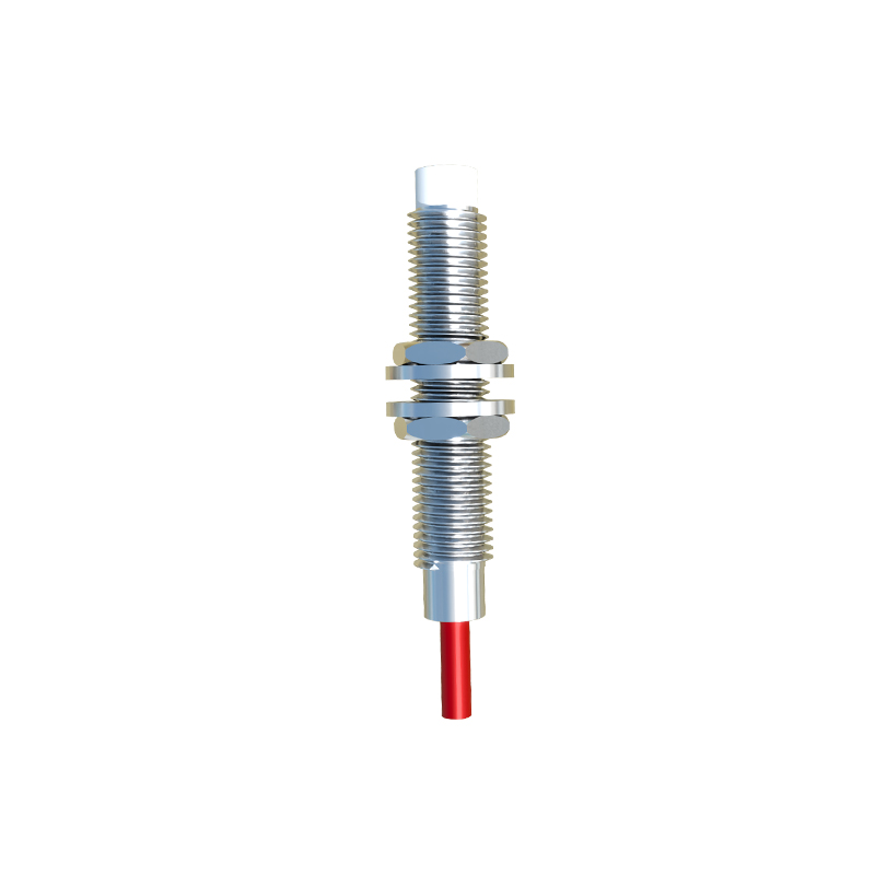
The calibration sequence varies slightly by technology. For a standard inductive proximity sensor with a teach-in function, the process begins by mounting the sensor and target material securely. Power the sensor and connect the measurement device to its output. Using the positioning stage, slowly bring the target to the desired operating point or "switch point." Once the target is at the exact required distance, activate the sensor's teach-in mode (often via a button or magnetic actuator). The sensor internally records the current signal level as its new switching threshold. For analog output sensors, the procedure involves setting the zero and span points. The zero point (often 4mA or 0V) is set with the target at the maximum sensing distance, while the span point (20mA or 10V) is set with the target at the minimum sensing distance. Always follow the manufacturer's specific instructions for multi-point calibration if high linearity is required.
Verification and Documentation of Calibration Results
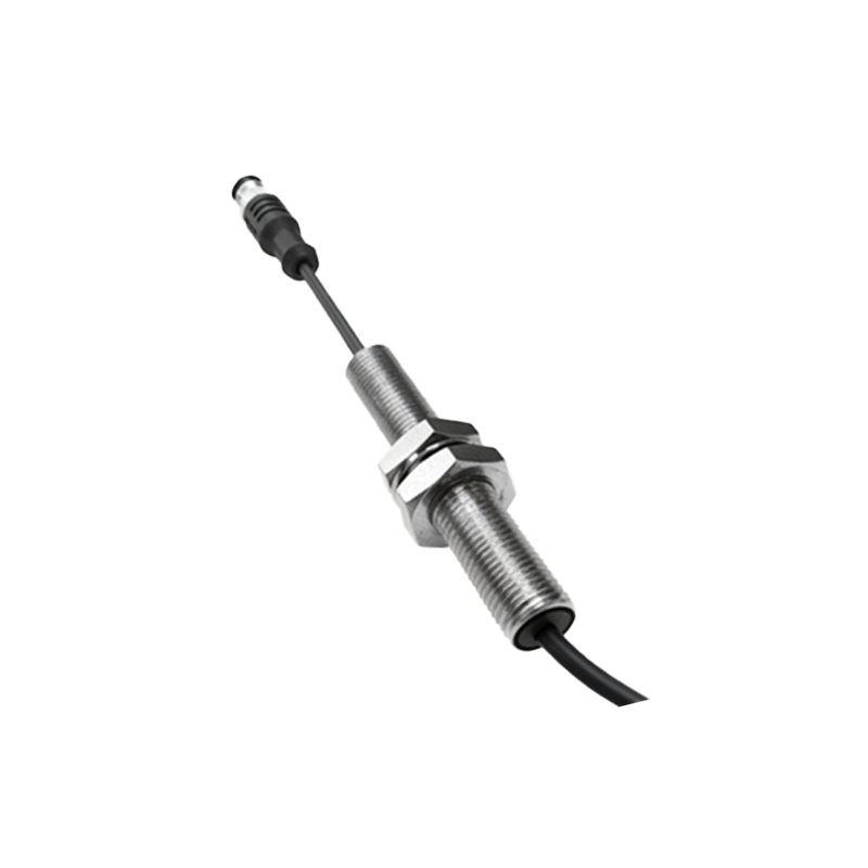
Calibration is not complete without verification. After adjusting the sensor, perform a verification run by moving the target through the entire range of interest and recording the sensor's output at several intervals. Compare these readings against the expected values. Key performance metrics to check include repeatability (the sensor's ability to consistently detect the target at the same point), hysteresis (the difference between the switch-on and switch-off points), and linearity error (for analog sensors). All findings must be meticulously documented in a calibration report. This report should include the sensor model, serial number, date, technician's name, environmental conditions, reference standards used, as-found data, as-left data, and the measured accuracy. This documentation is crucial for quality audits, traceability, and predictive maintenance schedules.
Troubleshooting Common Calibration Challenges
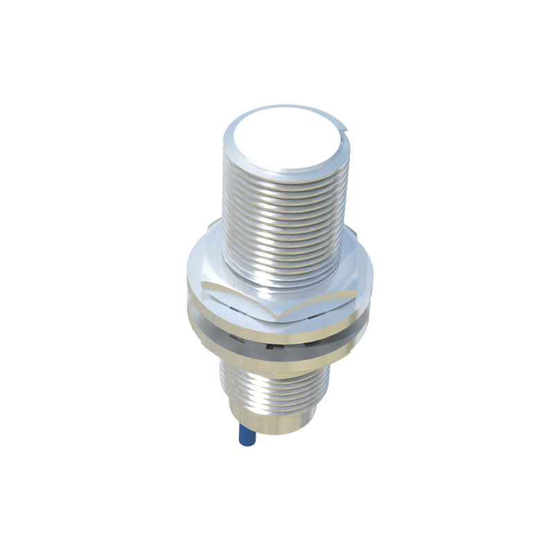
Several issues can arise during calibration. A frequent problem is inconsistent readings, often caused by an unsuitable target material, size, or shape. Ensure the target meets the sensor's specifications for minimum size and material composition. Electrical noise can also corrupt signals, manifested as erratic switching or analog signal drift. Employ proper shielding, grounding, and separation from power lines. If a sensor cannot be adjusted to the required range, it may be due to physical damage, aging internal components, or being fundamentally unsuited for the application (e.g., wrong sensing technology). Temperature drift is another concern; some sensors may require compensation or calibration at the operational temperature. Always allow sensors to acclimate to the ambient temperature of the calibration environment before starting.
Implementing a Proactive Calibration Schedule
Calibration is not a one-time event. To maintain long-term system integrity, implement a proactive calibration schedule based on the sensor's criticality, operating environment, and manufacturer's recommendations. Sensors in harsh conditions (high temperature, vibration, corrosive atmospheres) require more frequent checks. A common practice is to perform calibration annually, but high-precision or safety-critical applications may demand quarterly or even monthly verification. Utilize the historical data from calibration reports to track sensor