What is a Proximity Sensor Coupler?
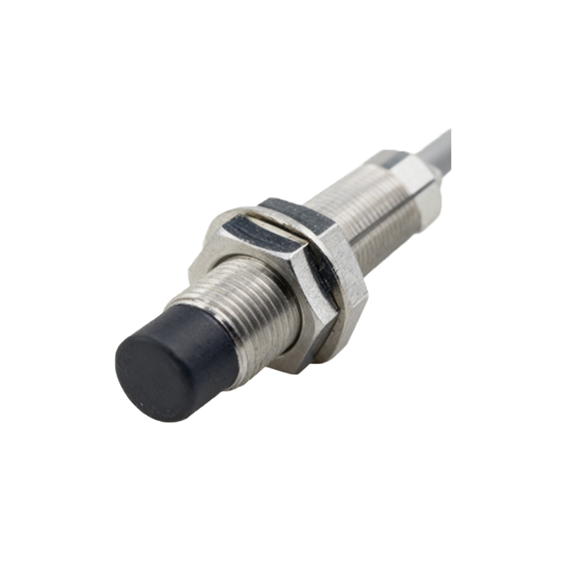
A proximity sensor coupler, often referred to as an interface module or connecting module, is a critical component in modern industrial control systems. It acts as an intermediary device between a standard proximity sensor (inductive, capacitive, or photoelectric) and a programmable logic controller (PLC) or other control unit. The primary function of the coupler is to condition the sensor's signal, providing electrical isolation, signal conversion, and amplification to ensure reliable and noise-free communication over longer distances. Essentially, it bridges the gap between the low-level, often non-standard output of a field sensor and the high-level, standardized input requirements of the control system. This decoupling protects sensitive control electronics from potential voltage spikes, ground loops, and electromagnetic interference (EMI) prevalent in harsh industrial environments.
Core Functions and Operational Principles
The operation of a proximity sensor coupler is based on solid-state electronics, typically involving opto-isolators or relay-based isolation. When a proximity sensor detects a target within its sensing range, it triggers a state change in its output circuit. This raw signal is fed into the coupler. Internally, the coupler's input stage electrically isolates this signal using an opto-isolator, where an LED is illuminated by the sensor signal, and a photosensitive transistor on the other side reacts to this light, creating a completely galvanically isolated replica of the signal. This isolated signal is then processed—often amplified or converted—to match the required output standard, such as a 24V DC transistor output, a relay contact, or a fieldbus-compatible signal like IO-Link. This process ensures that the final signal sent to the PLC is clean, stable, and at the correct voltage and current levels.
Key Advantages in System Design
Implementing proximity sensor couplers offers several significant advantages. First and foremost is enhanced system protection and reliability. The electrical isolation barrier prevents faults in the sensor wiring or the sensor itself from damaging the expensive PLC input cards. Secondly, they provide remarkable flexibility. A single coupler module can often connect multiple sensors (e.g., 2, 4, or 8 channels), reducing wiring complexity, cabinet space, and overall cost compared to running individual cables for each sensor back to the main control panel. Furthermore, couplers enable the use of sensors with different output types (e.g., NPN or PNP) on the same control system by standardizing the output to a uniform signal. They also facilitate easier troubleshooting with built-in LED indicators for power and channel status.
Common Types and Configurations
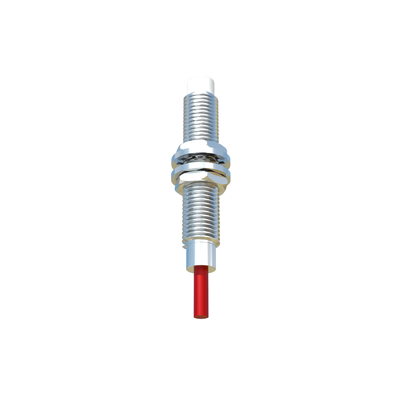
Proximity sensor couplers come in various types to suit different applications. The most basic classification is by the number of channels, ranging from single-channel units to multi-channel blocks. They are also categorized by their input compatibility (supporting AC or DC sensors, specific voltage ranges) and their output type. Common output configurations include relay outputs (for switching AC loads), transistor outputs (for fast DC switching), and analog outputs. A growing category is the intelligent coupler or IO-Link hub. These advanced modules not only provide switching functionality but also enable bidirectional digital communication, allowing for parameter setting, diagnostics, and process data exchange from the sensor directly to the control system, paving the way for Industry 4.0 applications.
Typical Application Scenarios
These devices are ubiquitous in automated manufacturing and processing plants. A classic application is in conveyor belt systems, where multiple proximity sensors monitor the position of products, detect jams, or count items. Instead of running dozens of wires to a central PLC, sensors are connected to locally mounted coupler modules. The couplers then transmit the consolidated signals via a single cable or a network connection. They are equally vital in machine tools for tool positioning and part detection, in automotive assembly lines for robotic cell safety interlocks, and in packaging machinery for precise fill-level control. In environments with high vibration or washdown requirements (like food & beverage), ruggedized coupler housings protect the connections and ensure operational integrity.
Selection Criteria and Installation Best Practices
Selecting the right proximity sensor coupler requires careful consideration of several parameters. Engineers must match the input voltage and type (sourcing vs. sinking) to the sensors being used. The output type and load capacity must be compatible with the PLC's input module or the load being controlled. Environmental factors like operating temperature, ingress protection (IP rating), and EMI resistance are critical for reliability. During installation, best practices include following the manufacturer's wiring diagrams precisely, ensuring proper grounding to minimize noise, and providing adequate ventilation if modules are densely packed in enclosures. Regular maintenance involves checking LED status indicators and ensuring terminal