Introduction to L355 Metal Proximity Sensors
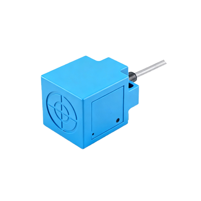
The L355 series represents a widely adopted line of inductive proximity sensors designed for detecting metallic objects without physical contact. These sensors operate on the principle of electromagnetic induction, where an oscillator circuit generates a high-frequency magnetic field. When a metal target enters this field, eddy currents are induced, causing a change in the oscillator's amplitude or frequency. This alteration is detected by a threshold circuit, which subsequently triggers a solid-state output switch. The L355 models are particularly valued for their robust construction, typically featuring a nickel-plated brass or stainless-steel housing that ensures reliable performance in harsh industrial environments, including those with exposure to oils, coolants, and dust. Their compact cylindrical form factor, such as the common M18 or M30 threaded barrels, facilitates easy integration into machinery and automated systems. Key specifications often include a sensing range of a few millimeters to several centimeters, depending on the specific model and target material, with factors like switching frequency and temperature range being critical for application suitability.
Core Circuit Architecture and Operating Principle
At the heart of an L355 sensor lies a carefully engineered electronic circuit. The primary components include an LC oscillator (inductor-capacitor), a demodulator, a trigger (or Schmitt trigger), and an output amplifier. The oscillator, centered around the sensing coil (the inductor), generates a constant high-frequency electromagnetic field at the sensor's active face. In the absence of a metal target, this oscillator runs at its resonant frequency. The demodulator circuit continuously monitors the oscillator's signal strength. Upon the approach of a conductive metal object, the induced eddy currents draw energy from the oscillator, leading to a dampening or frequency shift of the oscillation. The demodulator converts this change into a DC voltage signal. This signal is then fed into a trigger circuit with hysteresis, which provides a clean, bounce-free digital signal to indicate target presence, effectively ignoring minor fluctuations or vibration noise. Finally, the output stage, which can be configured as NPN (sinking) or PNP (sourcing) transistor outputs, switches the load connected to the sensor, such as a PLC input, relay, or indicator lamp.
Wiring Configurations and Electrical Interfaces
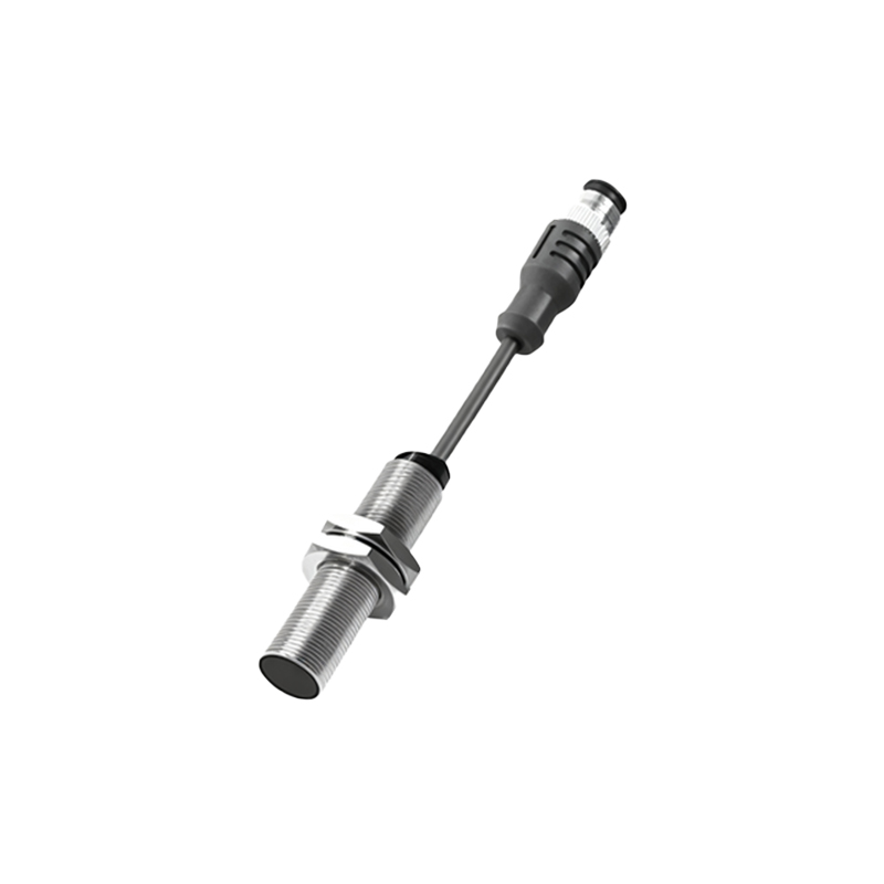
L355 sensors are available in multiple wiring configurations to match different control system standards. The most common are 3-wire DC versions. In a 3-wire DC setup, the wires are typically color-coded: brown for positive supply voltage (V+), blue for common negative (0V or ground), and black for the switched output signal. For an NPN output type, the black wire connects the load to ground when active (sinking current). Conversely, for a PNP output, the black wire supplies positive voltage to the load when active (sourcing current). Some models may also offer 2-wire AC/DC or 4-wire versions with dual complementary outputs. Proper wiring is crucial and must adhere to the manufacturer's datasheet. Key electrical considerations include the operating voltage range (e.g., 10-30V DC), current consumption, and the maximum load current of the output switch. It is standard practice to include a protective element, such as a flyback diode for DC inductive loads or a surge suppressor for AC loads, in the circuit to safeguard the sensor's solid-state output from voltage transients.
Factors Influencing Sensing Performance and Range
The effective sensing distance (Sn) of an L355 sensor is not a fixed absolute value but is influenced by several factors. First is the target material. Ferrous metals like mild steel provide the standard sensing range. Non-ferrous metals such as aluminum, brass, or copper typically reduce the effective range, often to 30-60% of the rated value, due to differences in conductivity and permeability. The target's size, shape, and orientation also play a role; a target larger than the sensor's face and approaching axially will yield the nominal range, while smaller or skewed targets reduce it. Environmental conditions are equally critical. Extreme temperatures can affect oscillator stability and component tolerances. The presence of strong external electromagnetic fields from motors or welding equipment may cause interference, necessitating proper shielding or increased mounting distance. Additionally, mounting the sensors in metallic surroundings requires careful attention to flush or non-flush mounting specifications to prevent the surrounding metal from influencing the magnetic field and causing false triggers or reduced sensitivity.
Typical Industrial Applications and Installation Best Practices
L355 metal proximity sensors are ubiquitous in factory automation. Common applications include position detection of machine parts (e.g., verifying a cylinder is retracted or extended), object counting on conveyor lines, limit switching, and rotary speed monitoring via