Understanding Series Connection for Proximity Sensors
Wiring proximity sensors in series is a common practice in industrial control circuits to achieve specific logical functions, primarily an AND condition. This configuration is often employed to enhance safety or process control by ensuring that multiple conditions are met before activating a load, such as a relay, solenoid, or PLC input. In a series circuit, the sensors are connected in a daisy-chain fashion where the output of one sensor provides the power path to the next. It is crucial to understand that this method is typically applicable only for two-wire AC or DC sensors, or for the load-switching side of three-wire sensors. The core principle is that current must pass through all sensors in the chain to complete the circuit and energize the final load. Any single sensor in the "off" state (target not detected) will break the circuit, preventing the load from operating. This setup is fundamentally different from parallel wiring, which creates an OR condition. Engineers choose series wiring for scenarios like two-hand safety controls on presses, multi-point access verification, or sequential process checks where simultaneous satisfaction of all sensor conditions is mandatory.
Key Considerations Before Wiring
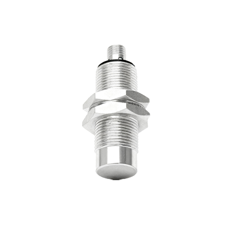
Prior to implementing a series connection, several critical factors must be evaluated to ensure reliable and safe operation. First, verify the sensor type and compatibility. Mixing different sensor types (e.g., AC with DC) or models with varying voltage drops and leakage currents in a single series string can lead to malfunction. Always consult the manufacturer's datasheet for specifications on maximum "off-state" leakage current and minimum "on-state" load current. In a series circuit, the cumulative leakage current of all sensors in their "off" state might be sufficient to falsely trigger a highly sensitive load like a PLC digital input. Conversely, the total voltage drop across all sensors when "on" must be considered to ensure sufficient voltage remains for the load to operate correctly. The total current draw of the load plus the sensors must not exceed the current rating of any single sensor in the chain. Furthermore, consider the operational logic: wiring in series creates a single point of failure for the "on" signal, which is desirable for safety but may complicate troubleshooting if a fault occurs.
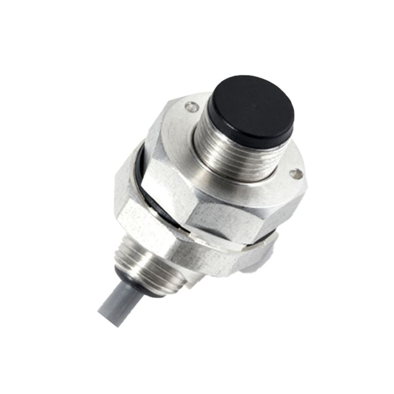
Step-by-Step Wiring Procedure for Two-Wire Sensors
For two-wire AC or DC proximity sensors, the wiring process is relatively straightforward. Begin by de-energizing and locking out the power supply to the entire circuit. Identify the load (e.g., a relay coil, K1) and the power source (L+ and L- for DC; L1 and Neutral for AC). Connect one power wire (e.g., L+) to the brown wire (typically positive or line) of the first proximity sensor (Sensor A). Then, connect the blue wire (typically negative or load) of Sensor A to the brown wire of the second proximity sensor (Sensor B). Continue this pattern if more than two sensors are used. Finally, connect the blue wire of the last sensor in the series string to one terminal of the load (e.g., relay coil). The other terminal of the load is then connected back to the remaining power wire (e.g., L-). In this configuration, power flows from the source, through Sensor A, then through Sensor B, then through the load, and back to the source. The load will only energize when both Sensor A AND Sensor B detect their respective targets, closing their internal switches simultaneously.
Wiring Three-Wire Sensors in Series for Load Control
Three-wire sensors (with separate power, ground, and output wires) are more commonly wired in parallel to a common power bus. However, their switching outputs can be wired in series to control a load. This involves connecting the load-switching side of the sensors in series, not their power supply lines. Provide independent power (e.g., 24V DC) to the brown (+) and blue (-) wires of each sensor as per standard practice. Then, take the black wire (output signal) from the first sensor (Sensor A) and connect it not directly to the load, but to the black wire of the second sensor (Sensor B). You essentially use the output wire of Sensor A as the "power in" for Sensor B's output switch. Finally, connect the black wire from Sensor B to the positive side of the load. The negative side of the load connects to the power supply negative (DC) or neutral (AC). This creates a series connection of the sensors' internal semiconductor switches. The same AND logic applies: both sensors must be active to complete the path to the load. Ensure the load current does not exceed the lower of the two sensors' output ratings.