Introduction to Proximity Sensors
Proximity sensors are non-contact electronic devices designed to detect the presence or absence of an object within a specific sensing range without any physical contact. These sensors are fundamental components in industrial automation, robotics, automotive systems, and consumer electronics. Their ability to operate reliably in harsh environments, provide high switching speeds, and offer long operational life makes them indispensable. The core principle involves generating an electromagnetic field or a beam of radiation and detecting changes in the field or return signal caused by a target object. This article delves into the typical internal structure and the underlying working principles of the most common types of proximity sensors.
Core Structural Components
While designs vary by type, a standard inductive or capacitive proximity sensor typically comprises several key internal components housed within a robust casing. The primary structure includes an oscillator circuit, a sensing coil or electrode, a signal conditioner, an output driver, and a power supply section. The oscillator generates a high-frequency electromagnetic field at the sensing face. The sensing coil (for inductive types) or electrode (for capacitive types) is the active element that projects this field into the surrounding space. The signal conditioner, which includes a demodulator and amplifier, processes the minute changes detected. The output driver, often a transistor or relay, switches the output state based on the processed signal. The entire assembly is potted with epoxy resin to protect against vibration, moisture, and contaminants.
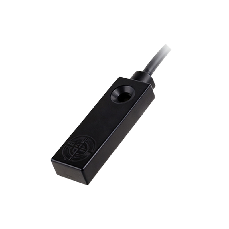
Inductive Proximity Sensor Principle
Inductive proximity sensors are used to detect metallic objects. The operating principle is based on electromagnetic induction. Internally, the oscillator generates a fluctuating magnetic field via the coil at the sensor's face. When a ferrous or non-ferrous metal target enters this field, eddy currents are induced on the surface of the metal. These eddy currents draw energy from the oscillator circuit, causing a reduction in the amplitude of oscillation. The demodulator circuit detects this amplitude drop. The subsequent amplifier circuit strengthens this signal to a level sufficient to trigger the output switching circuit, changing the sensor's output state (e.g., from OFF to ON). The sensor returns to its original state once the target moves out of the sensing range.
Capacitive Proximity Sensor Principle
Capacitive proximity sensors can detect both metallic and non-metallic materials, such as liquids, plastics, or wood. Their operation relies on changes in capacitance. The sensor's active face consists of two metallic electrodes forming an open capacitor, connected to an oscillator. The capacitance of this system changes when any material with a different dielectric constant than air approaches the sensing face. This change alters the oscillation amplitude or frequency. The circuit monitors this alteration. When the change exceeds a preset threshold, the output circuit is activated. Some capacitive sensors feature a sensitivity adjustment potentiometer to fine-tune the detection threshold for different materials or to compensate for background effects.
Photoelectric Sensor Structure and Principle
Photoelectric proximity sensors operate on an optical principle. Their structure includes a light emitter (usually an LED producing visible red, infrared, or laser light) and a photodetector (phototransistor or photodiode). In the through-beam type, emitter and detector are separate units; breaking the beam indicates an object. In the retro-reflective type, both are in one housing, using a reflector. The diffuse (proximity) type has both in one unit, detecting light reflected directly from the target. The principle involves the emitter projecting a light beam. The presence of an object interrupts, reflects, or attenuates this beam. The photodetector converts the received light intensity into an electrical current. A comparator circuit then evaluates this signal against a reference to control the output switch.
Magnetic (Reed Switch/Hall Effect) Principle
Magnetic proximity sensors detect permanent magnets. Two common structural types exist. The reed switch type contains two ferromagnetic reeds sealed in a glass tube with inert gas. When a magnet approaches, the reeds magnetize and attract each other, making contact to close a circuit. The Hall Effect type is solid-state, containing a semiconductor chip (Hall element), a voltage regulator, and an amplifier. When exposed to a magnetic field of sufficient strength, the Hall element generates a small voltage (Hall voltage) proportional to the field strength. This voltage is amplified and used to trigger a switching output. Magnetic sensors are highly reliable for position detection in clean environments.
Output Configuration and Wiring
The electrical output is a critical part of the sensor's structure. Common configurations include NPN (sinking) and PNP (sourcing) transistor outputs for DC sensors, and 2-wire AC/DC or 3-wire AC for alternating current models. In a 3