Understanding the Core Principle of Proximity Sensing
At its most fundamental level, a proximity sensor triggers by detecting the presence or absence of a target object within its specified sensing range without any physical contact. This detection event causes a change in the sensor's internal state, which is then converted into an electrical output signal. The specific triggering mechanism is intrinsically linked to the sensor's underlying technology. The absence of mechanical contact is the defining characteristic, enabling high reliability, long operational life, and suitability for harsh environments where dirt, oil, or vibration are present. The trigger point is precisely defined by the sensor's nominal sensing distance (Sn), a critical parameter specified under standardized conditions of target material, size, and temperature.
Inductive Proximity Sensors: Triggering via Eddy Current Damping
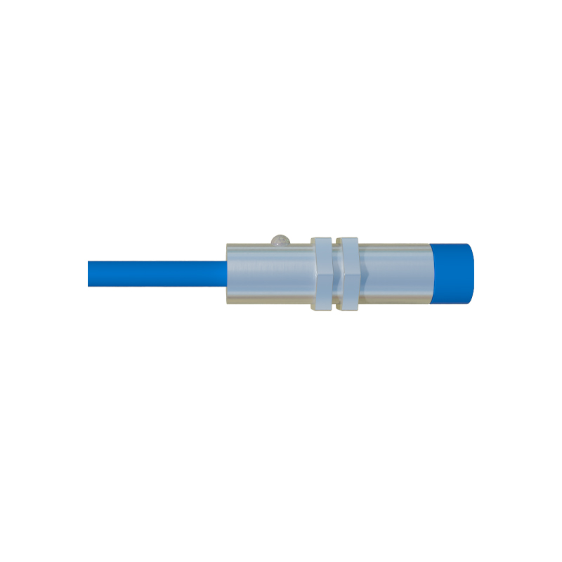
Inductive proximity sensors are designed to detect metallic targets, primarily ferrous metals like steel and iron, though many can also sense non-ferrous metals like aluminum or copper at a reduced range. The core component is a coil wound around a ferrite core, forming part of an oscillator circuit. When powered, this oscillator generates a high-frequency electromagnetic field at the sensor's active face. When a conductive metal target enters this oscillating field, eddy currents are induced on the target's surface. These eddy currents draw energy from the oscillator through electromagnetic damping. This energy loss causes the oscillation amplitude to decrease. A subsequent threshold circuit monitors this amplitude. Once the damping reaches a pre-set threshold—corresponding to the target being at the specified sensing distance—the circuit triggers, switching the sensor's solid-state output (PNP/NPN). The sensor resets when the target moves away, allowing the oscillator to resume full amplitude.
Capacitive Proximity Sensors: Triggering via Capacitance Change
Capacitive sensors can detect a much wider variety of materials, including metals, plastics, glass, wood, and liquids. They operate by generating an electrostatic field from a sensing electrode, which acts as one plate of a capacitor. The target object acts as the other plate, with the air gap as the dielectric. As a target approaches the active face, it alters the dielectric constant of the space between the electrodes, increasing the capacitance of the system. This sensor incorporates the sensing electrode into an RC oscillator circuit or a similar capacitance-measuring circuit. The increasing capacitance changes the circuit's characteristics, typically affecting the oscillation frequency or charge/discharge time. A monitoring circuit detects this change. When the capacitance change exceeds a configured sensitivity threshold, the circuit triggers and changes its output state. The sensitivity adjustment, often a potentiometer, allows tuning the trigger point for different material types and densities.
Magnetic Proximity Sensors (Reed Switch & Hall Effect)
Magnetic proximity sensors trigger in the presence of a magnetic field, usually from a permanent magnet attached to the moving target. Reed switch sensors contain two ferromagnetic reeds sealed in a glass tube filled with inert gas. When an external magnetic field of sufficient strength is applied, the reeds magnetize, attract each other, and make physical contact, closing the circuit to trigger an output. Removal of the magnetic field allows the reeds' spring tension to separate them, breaking the circuit. Hall Effect sensors, in contrast, are solid-state. They contain a semiconductor element. When exposed to a magnetic flux density exceeding its operate point (Bop), the Lorentz force deflects charge carriers within the semiconductor, generating a voltage difference known as the Hall voltage. An integrated circuit amplifies this voltage and compares it to a threshold. When exceeded, it triggers a clean digital output switch. Hall Effect sensors offer faster switching, unlimited life cycles, and precise, repeatable trigger points.
Photoelectric Sensors: Triggering via Light Beam Interruption or Reflection
Photoelectric sensors use light, typically infrared or visible LED-based, to detect objects. Their triggering method varies by operating mode. In a through-beam (opposed) mode, the sensor triggers when the target object physically interrupts the light beam traveling from a separate emitter to a receiver. In retro-reflective mode, the sensor triggers when the target breaks the beam reflected from a reflector back to the receiver. In diffuse (proximity) mode, the most common for standard proximity sensing, the sensor relies on light reflected directly off the target itself. The receiver monitors the intensity of the returning light. When a target enters the sensing field, the amount of reflected light increases. An internal circuit compares this intensity to a calibrated threshold. Once the received light energy surpasses this threshold, the sensor triggers its output. Background suppression and foreground suppression variants use triangulation principles to define a precise trigger plane, ignoring objects beyond or before a set distance.