Understanding Calibration Fundamentals
Calibration is the systematic process of configuring a proximity sensor to accurately detect a specific target at a defined sensing distance. This process establishes a reference point, or "calibration value," which ensures the sensor's output switches reliably at the correct moment. Unlike simple installation, calibration accounts for variables such as target material, size, shape, and environmental conditions. The core principle involves adjusting the sensor's sensitivity threshold to distinguish between the presence and absence of the target within its nominal range. For inductive sensors, this is heavily influenced by the target's material and size; for capacitive sensors, factors like material density and dielectric constant are critical. Proper calibration minimizes false triggers and missed detections, which are common causes of machine downtime and production errors in automated systems.
Key Factors Influencing Calibration Values
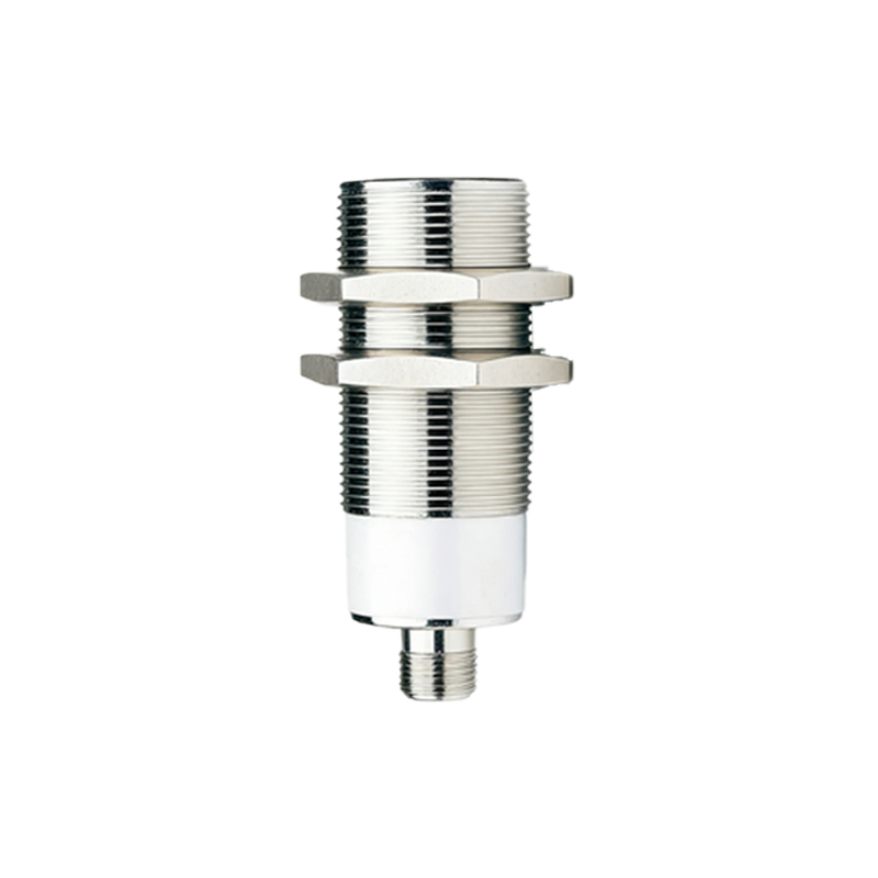
Several critical parameters directly impact the optimal calibration setting for a proximity sensor. The target material is paramount for inductive sensors, with steel providing the longest sensing distance, while aluminum, brass, and copper require significant reduction factors. The target size and shape also matter; a standard sensor is calibrated for a square steel target of a defined size. Smaller or irregularly shaped targets necessitate recalibration. Environmental conditions like temperature extremes, humidity, and the presence of contaminants (oil, dust, coolant) can drift the sensor's performance. Electrical noise from nearby motors or frequency drives can also interfere with signal integrity, requiring calibration in the actual operating environment to ensure stability.
Step-by-Step Calibration Procedure
A standardized calibration procedure is essential for repeatable results. First, mount the sensor securely in its final operational position. Connect it to the appropriate power supply and monitoring device, such as a PLC input or a pilot light. Introduce the standard target material to the sensor face at the exact required sensing distance. Using a non-metallic adjustment tool, slowly turn the sensor's potentiometer or follow the manufacturer's digital calibration routine. Adjust until the output indicator (LED) precisely switches states at the desired point. It is crucial to perform a "teach" procedure for both the "on" and "off" points to establish a hysteresis band, preventing output oscillation. Finally, validate the calibration by moving the target in and out of the sensing range multiple times at varying speeds to ensure consistent switching.
Utilizing Calibration Modes and Features
Modern proximity sensors offer advanced calibration modes to simplify setup. The "Teach-In" mode is most common, where the sensor automatically learns and stores the calibration value when the target is presented at the desired position. Some models feature a two-point teach for setting precise switch-on and switch-off points, defining the operational hysteresis. "Window" mode allows setting upper and lower limits for applications like part presence verification or thickness monitoring. For analog output sensors, calibration involves scaling the 4-20mA or 0-10V output range to correspond with the minimum and maximum measured distances. Understanding and correctly applying these built-in features drastically reduces setup time and improves accuracy.
Verification, Documentation, and Maintenance
Post-calibration verification is a non-negotiable quality step. Use calibrated gap plates or certified targets to verify the sensing distance under controlled conditions. Document all calibration data, including the date, technician, sensor model, serial number, target specifications, environmental conditions, and the final calibration value or potentiometer position. This creates a traceable history for predictive maintenance. Schedule periodic recalibration based on the sensor's criticality and operating environment. Sensors in high-vibration, high-temperature, or dirty environments may require more frequent checks. Trend analysis of calibration values over time can predict sensor degradation before a failure occurs, enabling proactive replacement.
Troubleshooting Common Calibration Issues
Persistent problems after calibration often point to specific root causes. If the sensor triggers erratically, check for electrical noise, grounding issues, or the presence of a different metallic object in the sensing field. A failure to detect the target may indicate an incorrect reduction factor for the material, a target that is too small, or a potentiometer adjusted beyond its functional range. Output signal drift over time typically suggests environmental factors like temperature changes or accumulation of debris on the sensor face. Always consult the sensor's datasheet for material-specific correction factors and ensure the power supply voltage is stable and within specifications, as low voltage can reduce effective sensing distance.