Introduction to the Core System
The DOF (Digital Output Format) simple infrared proximity sensor four-wheel car represents a foundational model in autonomous robotics and embedded systems education. This system integrates basic locomotion with elementary environmental sensing to create a vehicle capable of simple obstacle avoidance. The core principle revolves around using infrared (IR) light to detect objects within a specified range and processing this digital signal to control the motion of a four-wheel differential drive chassis. The architecture is deliberately simplified, focusing on clear input-output relationships, making it an excellent platform for understanding sensor integration, microcontroller programming, and real-time reactive control logic in a tangible, hands-on project.
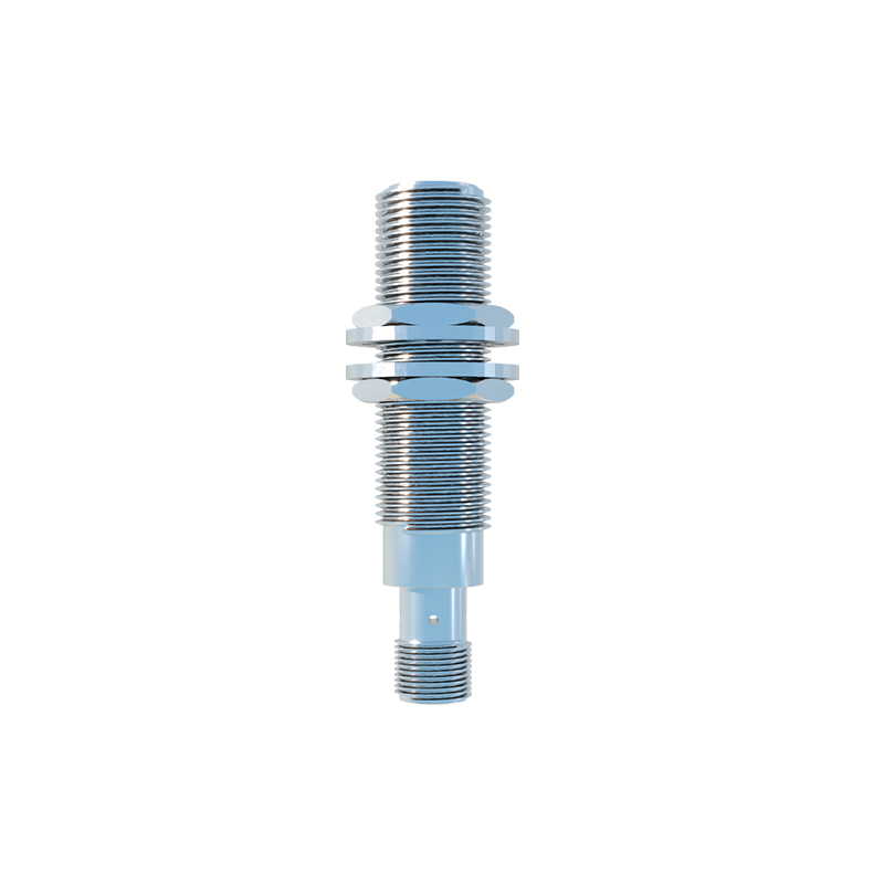
Working Principle of the IR Proximity Sensor
At the heart of the system is the digital output infrared proximity sensor. This sensor typically contains an IR LED emitter and a phototransistor receiver. The emitter constantly pulses infrared light, which is invisible to the human eye. When an object enters the sensor's detection field, a portion of this IR light is reflected back to the phototransistor. The sensor's internal circuitry compares the intensity of the reflected light to a pre-set threshold. If the intensity is sufficient, indicating an object is within the calibrated proximity range, the sensor's output pin switches from a high logic state to a low logic state, or vice versa, providing a clean digital signal. This digital on/off signal, as opposed to a variable analog reading, simplifies the code required for the microcontroller, as it only needs to read a HIGH or LOW value to determine the presence of an obstacle.
Microcontroller as the Central Processing Unit
A microcontroller, such as a common Arduino board or an STM32 chip, acts as the central processing unit. It continuously polls the digital input pins connected to the IR sensors. A typical setup might involve two sensors mounted on the front-left and front-right of the car. The program running on the microcontroller, often written in C/C++ or a derivative, contains the primary control algorithm. This algorithm is a loop that repeatedly checks the sensor states. The logic is straightforward: if both sensors read "clear" (no obstacle detected), the microcontroller sends signals to the motor driver to move both sets of wheels forward. If one sensor detects an obstacle, the car must react to avoid a collision.
Differential Drive and Maneuvering Logic
The four-wheel chassis usually employs a differential drive system, where the left and right wheels are controlled independently by separate motors. This design enables directional control through speed variation. The reactive logic programmed into the microcontroller leverages this capability. For instance, if the left IR sensor detects an obstacle while the right sensor is clear, the control algorithm will command the right-side motors to stop or reverse while the left-side motors continue forward or also stop. This action causes the car to pivot away from the obstacle on the left, effectively turning right. Conversely, an obstacle on the right triggers a left turn. If both sensors detect an obstacle simultaneously, the standard logic is to command all motors to reverse for a short duration, then turn sharply in a predetermined direction before attempting to move forward again.
Circuit Integration and Power Management
The electronic circuit forms the nervous system of the car. The microcontroller is powered by a regulated voltage source, often a battery pack. The digital output pins of the IR sensors connect directly to the microcontroller's digital input pins. The microcontroller's output pins, however, cannot supply enough current to drive DC gear motors directly. Therefore, a motor driver module, such as an L298N or a TB6612FNG, is essential. This driver acts as a high-power switch, using control signals from the microcontroller (often simple HIGH/LOW signals for direction and a PWM signal for speed) to manage the high current flow from the main battery to the motors. Proper power decoupling is crucial to prevent noise from the motors from interfering with the sensitive sensor and microcontroller circuitry.
Applications and Educational Value
This DOF IR sensor car, while simple, demonstrates core concepts in mechatronics and robotics. Its primary application is in educational settings, teaching students the fundamentals of sensor-based feedback loops, embedded programming, and basic control theory. It serves as a stepping stone to more complex autonomous systems involving analog sensors, sensor fusion, and advanced pathfinding algorithms. The principle of using a simple digital on/off signal for decision-making is foundational. By modifying the sensor placement, increasing the number of sensors, or enhancing the control logic, this basic platform can be adapted for line-following, edge detection, or simple maze-solving tasks, showcasing the versatility of integrating simple digital sensors with mechanical actuators.