Understanding Signal Attenuation and Interference
Extending the signal from a proximity sensor to a Programmable Logic Controller (PLC) over a distance of 50 meters presents a classic challenge in industrial automation. The primary concerns are signal attenuation and electromagnetic interference (EMI). Standard two-wire DC sensors, particularly those with low current outputs (e.g., 200mA or less), experience voltage drop over long cable runs. This drop can cause the sensor's output to fall below the PLC input module's minimum "ON" voltage threshold, leading to unreliable operation. Furthermore, long cables act as antennas, picking up EMI from motors, variable frequency drives (VFDs), and power lines, which can induce false signals on the sensor line.
Selecting the Right Sensor Technology
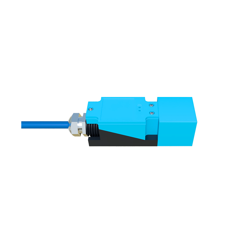
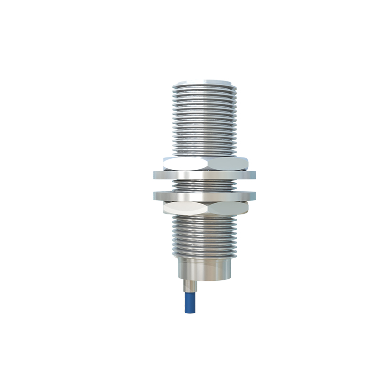
The choice of sensor technology significantly impacts performance over distance. Standard DC PNP or NPN sinking/sourcing sensors are most susceptible to voltage drop. For 50-meter runs, consider sensors with a higher switching capacity or those specifically designed for long-distance operation. Analog sensors (4-20mA) are inherently more robust for long distances because the current signal is less affected by voltage drop compared to a voltage signal. Alternatively, sensors with built-in amplifiers or short-circuit protection often have stronger output stages that can better drive longer cables.
Optimizing Cable Selection and Installation
Cable choice is critical. Always use shielded, twisted-pair cable. The twisting helps cancel out induced EMI, and the shield must be grounded at only one end—typically at the PLC cabinet—to prevent ground loops. Ensure the cable conductor size (AWG) is sufficient; a larger cross-sectional area (e.g., 18 AWG or 16 AWG) reduces resistance and minimizes voltage drop. During installation, strictly adhere to separation guidelines: route sensor cables away from power cables, motor leads, and VFD output cables. A minimum separation of 30 cm is recommended, and crossing should be at a 90-degree angle if unavoidable.
Implementing Signal Conditioning and Repeaters
When voltage drop is the main issue, a simple solution is to use a relay as a signal repeater. Install an interposing relay close to the sensor. The sensor switches the relay coil, and the relay's contacts, powered by a local source near the PLC, carry the signal to the PLC input. This isolates the long cable run from the sensor's limited output capacity. For environments with extreme EMI, dedicated signal conditioners or isolators are recommended. These devices convert the sensor signal, provide galvanic isolation, and output a clean, amplified signal to the PLC, effectively rejecting noise.
Utilizing Networked and IO-Link Solutions
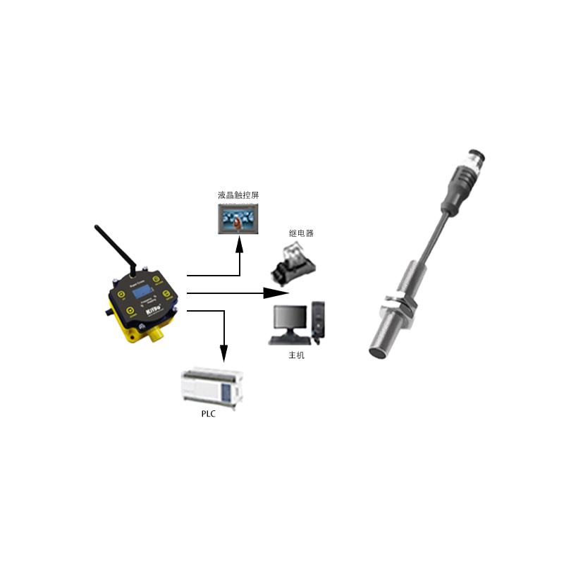
For modern systems, moving away from direct wiring is often the most robust solution. Deploying a networked I/O block near the group of sensors converts their signals to a digital protocol like PROFINET, EtherNet/IP, or Modbus TCP. A single Ethernet cable can then run the 50+ meters back to the PLC, immune to the analog interference issues. Alternatively, IO-Link sensors offer a compelling upgrade. An IO-Link master module placed near the sensors communicates digitally with them over a standard 3-wire cable (up to 20 meters per sensor), and the master then connects to the PLC via a fieldbus or Ethernet, handling the long-distance communication reliably.
Verifying System Performance and Diagnostics
After installation, thorough verification is essential. Use a digital multimeter to measure the voltage at the PLC input terminal when the sensor is activated. Ensure it is well above the PLC's guaranteed "ON" level under full load. Monitor the system for erratic behavior during the startup of large motors or VFDs. Many modern PLCs and networked I/O systems provide detailed diagnostic data, such as signal quality or cycle counters, which can be invaluable for preemptive maintenance. Always document the solution implemented, including cable types, routes, and device part numbers, for future troubleshooting.