Understanding Proximity Sensor Interference
Proximity sensors are fundamental components in modern automation, providing non-contact detection of metallic or non-metallic objects. However, their reliable operation can be significantly compromised by various forms of electrical and environmental interference. Interference typically manifests as false triggering, failure to detect, or erratic output signals, leading to production downtime, quality issues, and potential safety hazards. The primary sources of interference include electromagnetic interference (EMI) from nearby motors, variable frequency drives (VFDs), and welding equipment; radio frequency interference (RFI); crosstalk between multiple sensors; and physical factors like vibration, temperature extremes, or the presence of conductive debris. A systematic approach to identifying and mitigating these interference sources is critical for maintaining system integrity.
Proper Sensor Selection and Installation
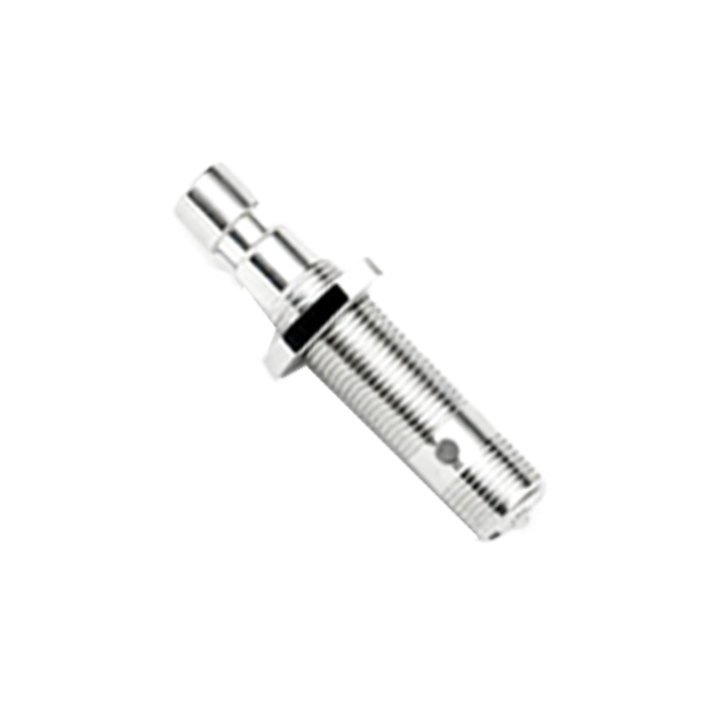
The first line of defense against interference begins with correct sensor selection and installation. Choose sensors with appropriate shielding, often denoted as "shielded" or "flush-mountable" types, which have a reduced sensing field on the sides, minimizing the chance of detecting adjacent metal structures or other sensors. For unshielded sensors, maintain the manufacturer's recommended minimum separation distances from each other and from metal mounting surfaces to prevent mutual interference and reduced sensing ranges. Always secure the sensor body firmly to dampen vibrations that can cause signal noise. Furthermore, ensure the sensing face is clean and free from build-up of oil, dust, or metallic swarf, as these can alter the sensor's effective sensing characteristics and behave as interference sources.
Optimizing Electrical Wiring and Grounding
Improper wiring is a leading cause of sensor malfunction. To minimize inductive and capacitive coupling from interference sources, always use shielded cables specifically designed for sensor applications. The cable shield must be grounded properly at only one end, typically at the controller or power supply side, to prevent ground loops which can introduce noise. Keep sensor cables as short as possible and route them away from high-power cables, motor leads, and power lines. A minimum separation of 20-30 cm is generally advised. If crossing is unavoidable, ensure the cables cross at a 90-degree angle to minimize the area of inductive coupling. Implement separate conduit or cable trays for signal and power lines as a best practice.
Implementing Noise Suppression Techniques
When interference is persistent, additional noise suppression components are necessary. For DC sensors, installing a flyback diode or a metal-oxide varistor (MOV) across the sensor's load can suppress voltage spikes from inductive loads like solenoids or relays. For AC circuits, an RC snubber network is often effective. Ferrite cores or beads clamped around the sensor cable near the connection points can absorb high-frequency RFI noise. In environments with severe EMI, such as near arc welders, consider using sensors with advanced diagnostics or built-in noise immunity features. Additionally, ensuring a stable, clean power supply with sufficient current capacity is crucial; voltage sags or ripple can be misinterpreted as signal interference.
Configuring and Tuning Sensor Parameters
Modern programmable sensors offer settings that can help overcome interference. The hysteresis setting, which is the difference between the switch-on and switch-off points, can be increased to prevent rapid, chatter-like switching caused by signal noise near the detection threshold. Similarly, adjusting the response time or delay functions can filter out brief, spurious signals. However, this must be balanced with the required process speed. For capacitive sensors detecting non-metals, the sensitivity potentiometer should be carefully adjusted to detect the target reliably while ignoring background materials or moisture. Always refer to the sensor's manual for specific tuning procedures to avoid creating new operational issues.
Systematic Troubleshooting and Validation
When interference is suspected, a methodical troubleshooting process is essential. Begin by isolating the sensor: disconnect it from the machinery and test it in a controlled, interference-free environment with a known target. If it operates correctly, the issue is external. Reconnect it and systematically power down nearby potential noise sources (e.g., drives, motors) one by one to identify the culprit. Use an oscilloscope to monitor the sensor's output signal and power lines for noise patterns. After implementing a solution, validate the system's performance under all normal and extreme operating conditions. Documenting the interference source and the applied countermeasure is invaluable for future maintenance and system expansion, ensuring long-term reliability of the automation system.