Introduction to M5 Smooth Shaft Proximity Sensors
The M5 smooth shaft proximity sensor represents a cornerstone of modern industrial automation, offering a compact and reliable solution for non-contact object detection. Characterized by its 5mm diameter threaded barrel and unshielded (smooth) sensing face design, this sensor variant is engineered for precise detection in tight spaces where metallic targets are present. Unlike shielded models, the M5 smooth shaft type provides an extended sensing range relative to its size, a critical feature for dynamic assembly lines and robotic applications. Its robust construction typically involves a nickel-plated brass or stainless-steel housing, ensuring resilience against coolants, oils, and mechanical impacts commonly found in manufacturing environments. The operational principle is predominantly inductive, generating an electromagnetic field that detects the presence of ferrous and non-ferrous metals, triggering a solid-state switch output without physical contact.
Key Technical Specifications and Performance
Understanding the technical parameters is vital for correct integration. A standard inductive M5 smooth shaft proximity sensor typically operates on a DC voltage range of 10-30V DC, with a nominal switching frequency reaching up to 5 kHz, enabling high-speed counting and positioning tasks. The rated sensing distance (Sn) for an M5 unshielded inductive sensor is usually up to 2 mm, though this can vary slightly by manufacturer and target material. Key performance metrics include hysteresis, which ensures stable switching by providing a differential between the switch-on and switch-off points, and repeat accuracy, often within microns. Temperature stability is another crucial factor, with operational ranges generally spanning from -25°C to +70°C, guaranteeing consistent performance in fluctuating industrial climates. The output configuration is commonly PNP normally open (NO) or normally closed (NC), providing compatibility with most programmable logic controllers (PLCs).
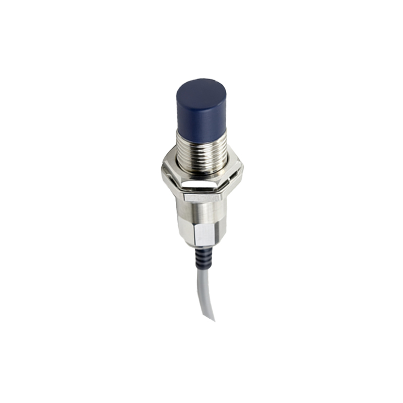
Advantages of the Unshielded (Smooth) Design
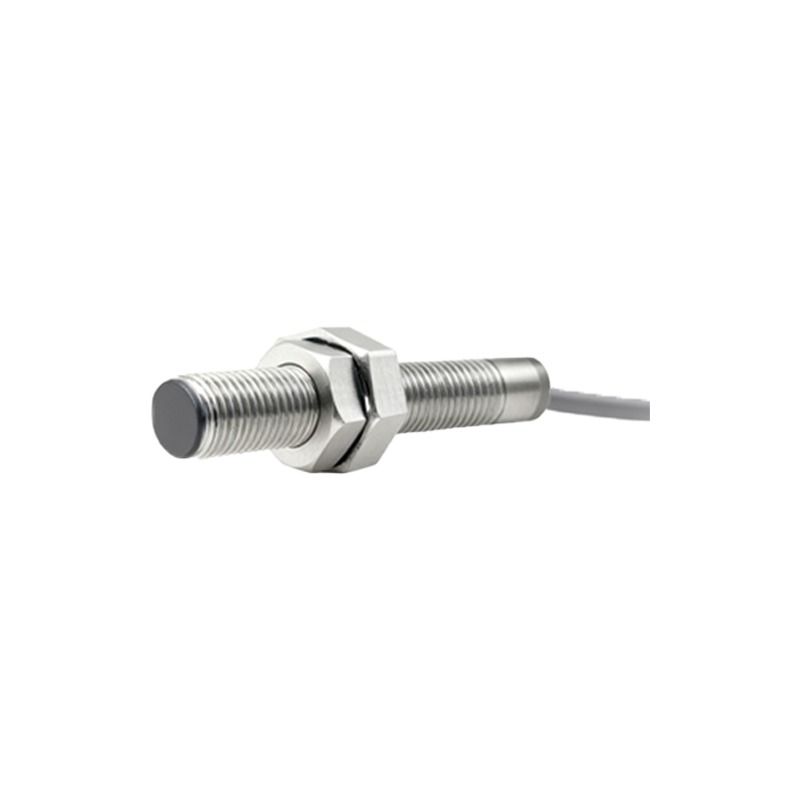
The defining feature of the "smooth shaft" or unshielded design is the absence of a metal ring surrounding the sensing face. This configuration allows the electromagnetic field to project laterally from the sensor body. The primary advantage is a significantly longer sensing range compared to a shielded M5 sensor of identical dimensions. This extended range provides greater installation flexibility and tolerance for mounting inaccuracies. Furthermore, the smooth shaft design allows for flush mounting in metallic brackets without the risk of the bracket itself being detected, which would cause false triggering in a shielded sensor. This makes it ideal for applications where the sensor must be recessed or protected within a metal fixture while maintaining its full sensing capability.
Typical Industrial Application Scenarios
The compact form factor and reliable detection of the M5 smooth shaft sensor make it indispensable across numerous sectors. In automated machinery, it is frequently deployed for end-position detection of pneumatic cylinders, verifying whether a piston has fully retracted or extended. Within precision assembly systems, these sensors perform critical part presence verification, such as confirming a screw is in place before a driver engages. They are also integral to high-speed counting systems on conveyor belts, detecting small metallic components or tags. In robotics, M5 sensors provide feedback for gripper jaw positioning or tool change confirmation. Their resilience also sees application in CNC machining centers for tool breakage detection and in packaging equipment for foil or metallic label detection.
Installation Guidelines and Best Practices
Correct installation is paramount for optimal performance and longevity. When mounting an M5 smooth shaft sensor, ensure there is adequate clearance around the sensing face. For unshielded models, maintain a minimum distance from surrounding metal objects—typically 2-3 times the sensor diameter—to prevent interference with the electromagnetic field. Utilize precision mounting brackets to avoid mechanical stress on the threaded barrel. Electrical wiring should follow EMC guidelines: use shielded cables for long runs, connect the shield to ground at the controller end, and keep sensor cables separate from high-voltage power lines to prevent electrical noise. Always adhere to the manufacturer's specified tightening torque for the M5 thread to avoid damaging the housing or compromising its IP rating, which is commonly IP67 for dust and temporary immersion protection.
Troubleshooting Common Operational Issues
Even robust sensors can encounter issues. A frequent problem is failure to detect the target. This can stem from an incorrect sensing distance, using a non-metallic target, or a target smaller than the sensor's sensing face. Verify the target material and size specifications. Another common issue is erratic switching or false triggers, often caused by electrical interference (noise) or the proximity of other metal objects within the sensor's lateral field. Re-routing cables and ensuring proper clearance can resolve this. If the sensor is damaged mechanically, check for dents or cracks in the housing. For electrical diagnostics, use a