Introduction to 3-Wire Proximity Sensors
In the realm of industrial automation and control systems, proximity sensors are indispensable components for non-contact detection of metallic or non-metallic objects. Among the various configurations available, the 3-wire proximity sensor stands out as one of the most common and versatile types. These sensors are fundamental for tasks such as position sensing, counting, and end-of-travel detection in machinery. Unlike their 2-wire counterparts, 3-wire sensors provide a distinct separation between the power supply and the output switching circuit. This architecture offers significant advantages in terms of performance, reliability, and ease of integration into complex control panels. The three wires typically correspond to a positive supply voltage (brown wire), a negative or ground connection (blue wire), and a switched output signal (black wire). This clear demarcation simplifies wiring, troubleshooting, and system design, making them a preferred choice for engineers designing robust automation solutions.
Internal Circuitry and Operating Principle
The core of a 3-wire DC proximity sensor consists of an oscillator circuit, a trigger stage, and an output switching device. The oscillator generates a high-frequency electromagnetic field at the sensor's active face. When a target object enters this field, eddy currents are induced in the target (if metallic), causing a change in the oscillation amplitude. This change is detected by the trigger circuit. Upon reaching a predefined threshold, the trigger activates the solid-state output switch. In a 3-wire sensor, this output is typically a transistor, either NPN (sinking) or PNP (sourcing). The power for the oscillator and trigger logic is drawn directly from the two supply wires, while the third wire is dedicated solely to carrying the load current from the output transistor. This isolated design minimizes interference between the sensitive detection circuitry and the load, leading to more stable operation and longer sensing ranges compared to 2-wire sensors.
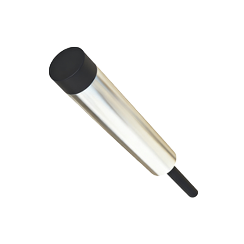
Wiring Configurations: NPN vs. PNP Outputs
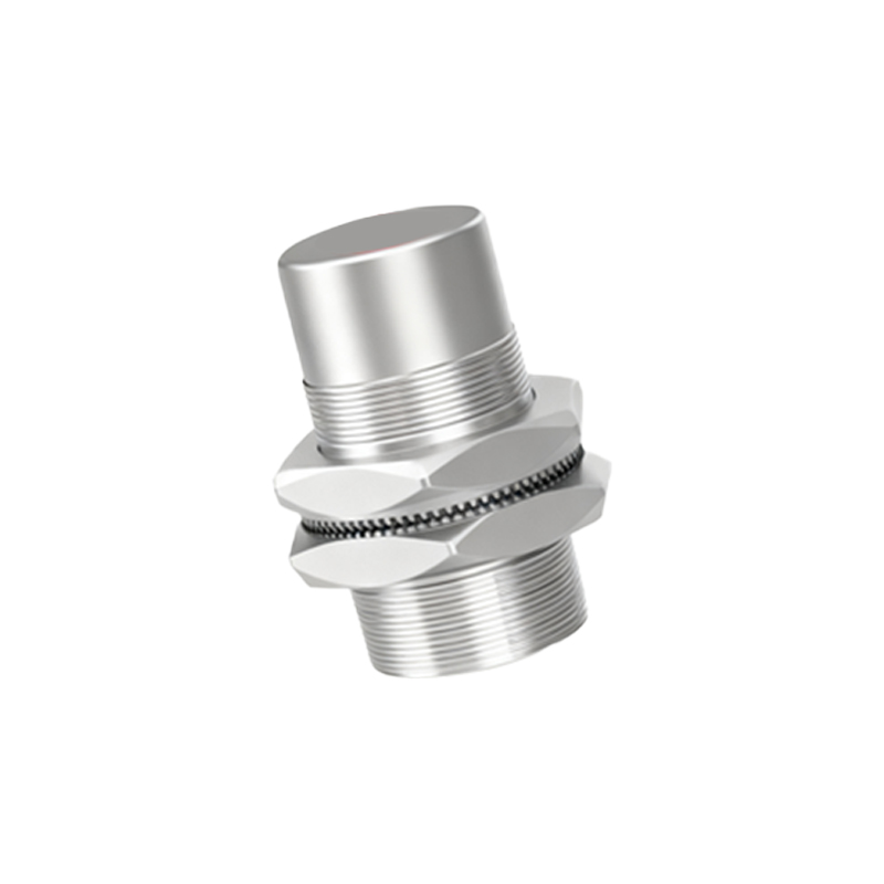
A critical distinction in 3-wire proximity sensors is the type of output transistor used, classified as either NPN or PNP. This classification determines how the sensor interfaces with the programmable logic controller (PLC) or other control devices. An NPN sensor, often referred to as a "sinking" sensor, switches the negative or ground side of the load. In this configuration, the load is connected between the positive supply and the sensor's output wire. When activated, the NPN transistor connects the output to ground, completing the circuit and allowing current to flow through the load. Conversely, a PNP sensor, or a "sourcing" sensor, switches the positive side. Here, the load is connected between the output wire and ground. When the PNP transistor activates, it connects the output to the positive supply, powering the load. The choice between NPN and PNP is primarily dictated by the input circuit design of the PLC or controller being used.
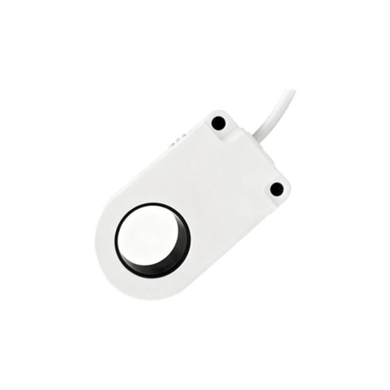
Key Advantages in Industrial Applications
The 3-wire design offers several compelling benefits that justify its widespread adoption. First, it provides a low leakage current in the "off" state, which is crucial for preventing false triggering in sensitive electronic inputs. Second, these sensors can handle higher switching frequencies, making them suitable for high-speed counting and inspection applications. Third, the dedicated output wire allows for a wider range of compatible load types, including low-power PLC inputs, relays, and indicator lamps. Furthermore, the voltage drop across the output transistor is minimal, ensuring that nearly the full supply voltage is available to the load. This is particularly important when operating at the lower end of the sensor's voltage range. The physical separation of circuits also enhances diagnostic capabilities, as problems with the power supply can be isolated from issues with the output switching function.
Installation Considerations and Best Practices
Proper installation is paramount to ensure optimal performance and longevity of 3-wire proximity sensors. Engineers must first verify the sensor's specifications, including operating voltage (commonly 10-30V DC), output type (NPN/PNP), and sensing range. It is essential to provide a stable, clean power supply, often with overvoltage and reverse polarity protection. When routing cables, keep sensor wires away from high-voltage power lines and motor leads to avoid electromagnetic interference. For metallic mounting surfaces, ensure a non-ferrous mounting bracket or provide adequate clearance (typically 1-2 times the sensor diameter) to prevent the mounting material from influencing the sensing field. Always refer to the manufacturer's datasheet for specific mounting dimensions, sensing characteristics for different target materials, and environmental ratings such as IP67 for protection against dust and water ingress.