Introduction to Proximity Sensor Operation
During the hands-on training session with inductive and capacitive proximity switches, the fundamental principle of operation was immediately observable. The inductive sensors, designed for metal detection, demonstrated a clear and reliable response when a ferrous metal target entered their sensing range. A distinct LED indicator on the sensor housing illuminated, and the output signal switched states. The reaction was swift and repeatable. Conversely, the non-ferrous metals like aluminum or copper required closer proximity or, in some cases, a specialized sensor variant, highlighting the importance of material selection in application design. The capacitive sensors showed their versatility by detecting both metallic and non-metallic materials, such as plastic or liquid levels through a container wall, though adjustments to the sensitivity potentiometer were often necessary to prevent false triggering from environmental factors.
Critical Factors Affecting Sensing Distance
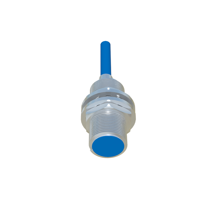
A core part of the实训 involved testing the rated sensing distance versus the actual effective sensing distance. The datasheet value, often listed for a standard mild steel target, was rarely achieved in a cluttered workshop environment. We observed that the presence of other metal objects in the background or adjacent to the sensor could significantly reduce the effective range. This "shielding effect" was particularly pronounced with inductive sensors. Furthermore, the size and shape of the target material proved crucial. A target smaller than the sensor's face or one approaching from the side required a much closer distance for reliable detection. Temperature variations also played a minor but measurable role, with extreme cold slightly increasing the sensing distance for some inductive models and heat affecting oscillator stability in capacitive units.
Output Configuration and Wiring Observations
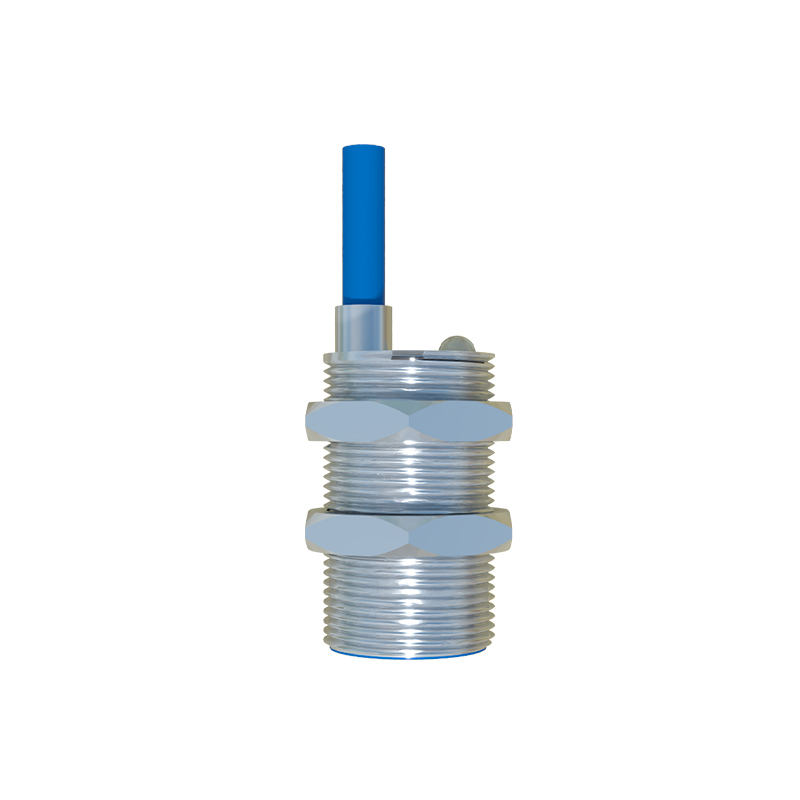
Wiring the sensors in both normally open (NO) and normally closed (NC) configurations provided practical insight into circuit design for safety and logic. Using a multimeter and a programmable logic controller (PLC) input module, we monitored the voltage transition. For a 3-wire DC sensor, the swift transition of the output transistor (sinking or sourcing) was confirmed. A common error observed was mismatching the sensor's output type (PNP vs. NPN) with the PLC input, resulting in no signal read. The importance of a stable, clean power supply was evident; voltage spikes or ripple on the DC line caused intermittent operation in some units. For 2-wire AC sensors, we noted the minimal residual current (leakage current) when in the "off" state, which must be considered when interfacing with sensitive control relays to avoid accidental energization.
Environmental Interference and Noise Immunity
The training setup intentionally introduced sources of electromagnetic interference (EMI), such as operating a large motor starter or welding equipment nearby. The inductive sensors, with their internal oscillator, sometimes exhibited erratic behavior or a chattering output when subjected to strong magnetic fields. Proper metal mounting of the sensor body and using shielded cables dramatically improved noise immunity. For capacitive sensors, the buildup of dust, moisture, or condensation on the sensing face consistently led to false triggers. This underscored the necessity of selecting sensors with appropriate IP (Ingress Protection) ratings for the operational environment and implementing regular maintenance schedules to keep the sensing face clean.
Response Time and Frequency Testing
Using an oscilloscope to measure the sensor's response time revealed critical data for high-speed applications. The switch-on and switch-off delays, though typically in the microsecond or low millisecond range, became a limiting factor when detecting rapidly moving objects on a conveyor. We tested the maximum switching frequency by passing a rotary metal disc with slots past the sensor. The sensor could reliably detect individual teeth up to a certain speed, beyond which it would miss pulses. This实训 highlighted that the published response time and frequency specifications are absolute maximums, and derating for a safety margin in a real application is a mandatory engineering practice.
Fail-Safe Considerations and Diagnostics
A valuable exercise involved simulating fault conditions. We disconnected wiring, shorted outputs, and observed the behavior of the sensor's diagnostic indicators, such as a continuous or flashing LED. Modern sensors with IO-Link or other digital communication capabilities provided detailed status information directly to the controller, a significant advantage over traditional models. We also discussed and observed the implications of wiring a sensor in a "dry contact" configuration versus a "solid-state" output for fail-safe design. The实训 concluded that understanding the sensor's failure modes—whether it fails open or closed—is paramount for designing systems that default to a safe state in the event of a sensor malfunction.