Understanding Normally Open Proximity Sensors
A normally open (NO) proximity sensor is a fundamental component in industrial automation. In its default, non-activated state, the output switch of an NO sensor is open, meaning no electrical current flows through the output circuit. When a target object enters the sensor's detection range, the internal switch closes, completing the circuit and allowing current to flow. This behavior makes NO sensors ideal for applications where an action should only occur upon detection, such as starting a process, activating a warning light, or incrementing a counter. The wiring for these sensors is straightforward but must be executed precisely to ensure reliable operation and system safety.
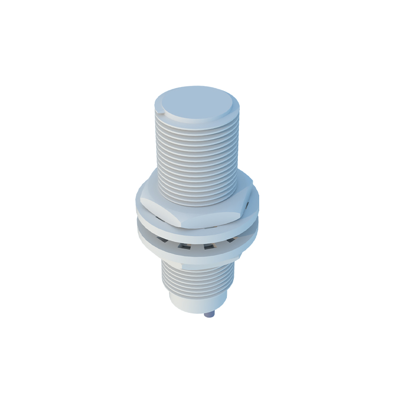
Key Components and Terminal Identification
Before examining the wiring diagram, it is crucial to identify the standard terminals on a three-wire DC proximity sensor, which is the most common type. These terminals are typically labeled as Brown (Br), Blue (Bu), and Black (Bk). The Brown wire is connected to the positive DC supply voltage (often +24V DC). The Blue wire is connected to the negative side of the power supply, or 0V (common). The Black wire is the switched output signal wire. In a normally open configuration, this Black wire will have voltage present (equal to the supply voltage) when no target is detected, and it will switch to connect to 0V (sinking) or to the supply voltage (sourcing) when a target is detected, depending on the sensor's output type (NPN or PNP).
Normally Open Wiring Diagram for NPN Output Type
An NPN output sensor is a current-sinking device. In a standard NO NPN wiring setup, the Brown wire connects to the positive DC supply (+V). The Blue wire connects to the supply common (0V). The Black output wire is connected to one side of the load (e.g., a PLC input, relay coil, or indicator lamp). The other side of the load is then connected back to the positive supply (+V). When no target is present, the circuit is open, and no current flows to the load. When a target is detected, the NPN transistor inside the sensor activates, effectively connecting the Black wire to 0V. This completes the circuit, allowing current to flow from +V, through the load, through the sensor's Black wire, and out to 0V, thereby activating the load.
Normally Open Wiring Diagram for PNP Output Type
A PNP output sensor is a current-sourcing device. For a NO PNP configuration, the power connections remain identical: Brown to +V and Blue to 0V. The critical difference lies in the load connection. The Black output wire is connected to one side of the load. However, the other side of the load is now connected to the supply common (0V). In the idle state, the circuit is open. Upon target detection, the internal PNP transistor switches, connecting the Black wire to the positive supply voltage (+V). Current then flows from the sensor's Black wire, through the load, and to 0V, powering the load. It is vital never to mix NPN and PNP wiring schemes with incompatible controllers, as this can cause malfunction or damage.
Connecting to a Programmable Logic Controller (PLC)
Integrating a normally open proximity sensor with a PLC is a common task. For a DC input module on a PLC, you must first determine if the module is designed for sinking (common positive) or sourcing (common negative) inputs. For an NPN (sinking) sensor, wire the Black output to the PLC input terminal. The common of the PLC input module should be connected to +V. For a PNP (sourcing) sensor, wire the Black output to the PLC input, and connect the module's common to 0V. In both cases, the sensor's Brown and Blue wires receive power independently. The PLC will read the input as "OFF" (or 0) when the sensor is idle (circuit open) and "ON" (or 1) when a target is detected (circuit closed).
Practical Installation and Safety Considerations
Always de-energize the circuit before beginning any wiring work. Use the correct wire gauge for the expected current load. Ensure tight connections to prevent arcing or voltage drop. Provide strain relief for cables to avoid pulling on terminal connections. Mount the sensor securely, paying close attention to its specified sensing distance and alignment relative to the target material. For metallic environments, use shielded cables and ground the shield properly at one end to minimize electrical noise interference, which can cause false triggering. Always consult the manufacturer's datasheet for