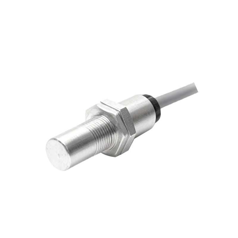
Understanding Proximity Sensor Module Fundamentals
A proximity sensor module is a self-contained electronic device designed to detect the presence or absence of an object within a specified sensing range without physical contact. These modules typically integrate the sensing element, signal conditioning circuitry, and output driver into a single unit. The core sensing technology can be inductive, detecting metallic objects; capacitive, detecting both metallic and non-metallic materials; or photoelectric, using light beams. The module's primary function is to provide a clean, amplified, and often configurable output signal—commonly a digital ON/OFF signal or an analog voltage/current—based on the detection event. This simplifies integration into larger control systems like Programmable Logic Controllers (PLCs), microcontrollers, or relay panels, as the complex signal processing is handled internally by the module itself.
Standard Wiring Configuration and Pin Definitions
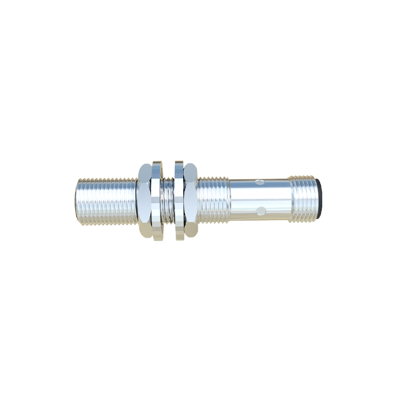
Most standard three-wire DC proximity sensor modules follow a universal color-coding and pinout scheme, which is critical for safe and correct installation. The three essential wires are: Brown (or Red), which connects to the positive DC supply voltage (typically +12V or +24V DC); Blue (or Black), which connects to the DC common or ground (0V); and Black (or White), which is the output signal wire. For a sinking (NPN) output module, the Black wire acts as the switched negative connection; when the sensor is active, it connects the load to ground. For a sourcing (PNP) output module, the Black wire acts as the switched positive connection; when active, it supplies voltage to the load. A fourth wire, often white or gray, may be present for a complementary output or an analog signal. Always consult the specific module's datasheet for absolute confirmation, as colors can vary by manufacturer.
Connecting to a PLC Digital Input
Integrating a proximity sensor with a PLC is a common industrial task. For a Sourcing (PNP) sensor module: Connect the Brown wire to the +24V DC supply. Connect the Blue wire to the 0V DC common, which is also connected to the PLC's common terminal for input cards. Connect the Black (output) wire directly to the designated PLC input terminal (e.g., I0.0). When the sensor detects an object, it sources +24V to the PLC input, registering a logic HIGH. For a Sinking (NPN) sensor module: Connect the Brown wire to +24V DC. Connect the Blue wire to 0V DC. Connect the Black (output) wire to the PLC input. However, the PLC input card's common must be connected to +24V. When active, the NPN sensor sinks current to 0V, pulling the PLC input low to register a logic HIGH (on a positive-logic, sinking-input card). Mismatching sensor output type and PLC input type is a frequent wiring error.
Interfacing with Relays and Loads
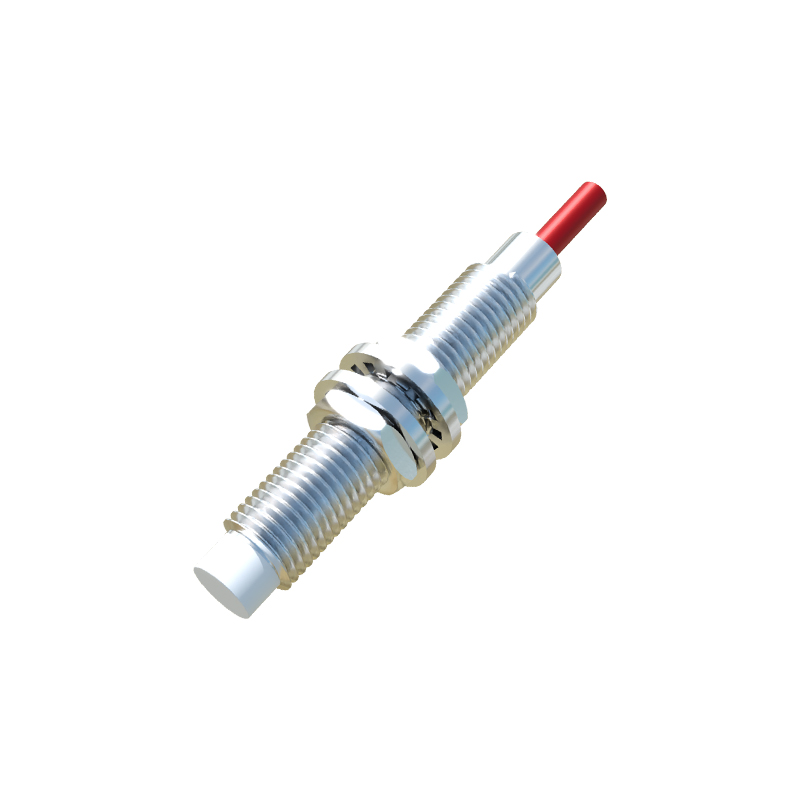
For direct control of relays, solenoids, or indicator lamps, the wiring must account for the load's voltage and current requirements relative to the sensor's rating. When using a PNP sensor to power a relay coil: Connect the Brown wire to +V, Blue to 0V. Connect one side of the relay coil to +V. Connect the other side of the coil to the sensor's Black output wire. The sensor acts as a switch for the positive side. A flyback diode should be placed in parallel with the relay coil (cathode to +V) to suppress voltage spikes. For an NPN sensor controlling a relay: Connect the Brown to +V, Blue to 0V. Connect one side of the relay coil to the sensor's Black output wire. Connect the other side of the coil directly to +V. Here, the sensor switches the ground path for the load. Always ensure the load's inrush and steady-state current is below the sensor's maximum switching capacity.
Power Supply Considerations and Noise Immunity
A stable, clean power supply is paramount for reliable sensor operation. Use a regulated industrial DC power supply with adequate current capacity. Implement proper filtering and protection at the system level. Always fuse the positive supply line close to the power source to protect the wiring. For noise reduction in electrically harsh environments, use shielded cable for the sensor wiring, especially over long runs. Connect the cable shield to earth ground at the control panel end only, avoiding a "pig-tail" connection. Keep sensor cables separate from high-voltage AC power lines and motor drive cables. If possible, use twisted pair wires for the supply and output. Many modules feature built-in protection against reverse polarity, short-circuit, and electrical interference, but external precautions