In the realm of industrial automation and quality control, achieving precise, non-contact measurement of material thickness is a critical challenge. Thickness laser displacement sensors have emerged as a premier solution, offering unparalleled accuracy, speed, and reliability for a vast array of applications. This article delves into the operational principles, key application areas, and essential selection criteria for these sophisticated instruments.
At its core, a thickness laser displacement sensor system typically employs two opposing laser displacement sensors precisely aligned on either side of the target material. Each sensor independently measures the distance to the material surface. By knowing the fixed distance between the two sensors (the gauge span) and subtracting the sum of the two measured distances, the system calculates the material's thickness with high precision: Thickness = Gauge Span - (Distance A + Distance B). The most common technology used is laser triangulation. A laser diode projects a focused spot of light onto the target surface. The reflected light is imaged onto a position-sensitive detector (PSD) or a CMOS/CCD array. Any change in the distance to the target causes the reflected spot to shift position on the detector, and this shift is converted into a precise distance measurement through trigonometric calculation. Advanced models utilize red or blue lasers, with blue lasers offering superior performance on transparent materials or hot surfaces by reducing penetration and diffraction effects.
The advantages of using laser-based systems for thickness gauging are numerous. They provide true non-contact measurement, eliminating any risk of damaging delicate or soft materials like films, foils, or rubber. They offer extremely high sampling rates, often in the kilohertz range, making them ideal for high-speed production lines such as rolling mills for metals or web processes for plastics and paper. Their measurement is largely independent of material color, reflectivity, or surface texture, especially with models featuring automatic gain control and advanced algorithms. Furthermore, they provide exceptional resolution, down to the sub-micron level, ensuring even the most minute thickness variations are detected.

Thickness laser sensors are indispensable across diverse industries. In metal manufacturing, they are deployed in hot and cold rolling mills to monitor and control the thickness of steel, aluminum, and copper strips in real-time, ensuring product consistency and reducing material waste. In the plastics industry, they measure extruded films, sheets, and coatings, critical for maintaining product quality and optimizing raw material usage. The paper industry relies on them for monitoring caliper (thickness) during production, which directly affects printability and opacity. In the production of lithium-ion battery electrodes, these sensors ensure the precise coating thickness of active materials on foil substrates, a key parameter for battery performance and safety. Additionally, they are used for measuring the thickness of glass panels, laminated materials, and various rubber products.
Selecting the appropriate thickness laser displacement sensor requires careful consideration of several parameters. First, define the measurement range and required resolution. The sensor must cover the expected thickness variation with enough overhead. Resolution determines the smallest detectable change. Second, consider the material properties. Is it transparent, translucent, or opaque? Hot or cold? Highly reflective or matte? For transparent materials (e.g., glass, clear film), a blue laser sensor is often mandatory. For hot metals, specialized models with protective purging and specific wavelength are needed. Third, the installation environment is crucial. Assess factors like ambient temperature, vibration, dust, and fumes. Sensors are available with robust housings (IP67 ratings are common) for harsh industrial environments. Fourth, evaluate the required response speed and data output. Ensure the sensor's sampling rate meets or exceeds the line speed. Standard analog outputs (4-20mA, 0-10V) and digital interfaces (Ethernet, RS-485) are typical for integration into PLCs or control systems. Finally, consider the mechanical design of the gauge frame. It must provide stable, vibration-resistant alignment of the two sensors. Thermal stability of the frame is vital to maintain calibration over temperature fluctuations.
Integration and calibration are final critical steps. Proper alignment of the two sensors is paramount; even a slight misalignment can introduce significant error. Many systems offer built-in software for automatic alignment and calibration using a master sample of known thickness. Regular calibration checks with certified standards are recommended to maintain long-term accuracy. The sensor data is typically fed into a control system that can provide real-time SPC (Statistical Process Control) charts, trigger alarms for out-of-spec conditions, and even form a closed-loop control system to adjust machinery like roller gaps automatically.
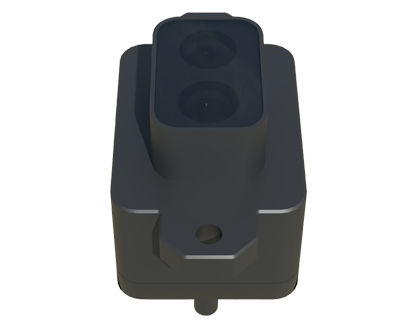
In conclusion, thickness laser displacement sensors represent a mature yet continuously advancing technology that is fundamental to modern manufacturing quality assurance. By enabling fast, accurate, and non-contact thickness measurement, they empower industries to enhance product quality, minimize material usage, and optimize production efficiency. Understanding their working principles, applications, and selection criteria is essential for engineers and technicians aiming to implement a successful and reliable measurement solution on the factory floor.