As an experienced electrical engineer specializing in industrial automation, I often encounter questions about interpreting proximity sensor fiber optic wiring diagrams. These diagrams are essential for proper installation, troubleshooting, and integration of sensors in various applications, from manufacturing lines to robotic systems. Understanding how to read them accurately ensures system reliability and safety.
First, recognize the standard symbols used in these diagrams. Proximity sensors with fiber optic components are typically represented by a combination of symbols: a rectangle or circle for the sensor body, lines indicating fiber optic cables, and specific icons for the sensing head. The fiber optic cable is often shown as a dashed or solid line with a light beam symbol. Look for labels such as "TX" (transmitter) and "RX" (receiver) to identify the light source and detection points. In some diagrams, arrows denote the direction of light transmission, which is crucial for aligning the sensor correctly.
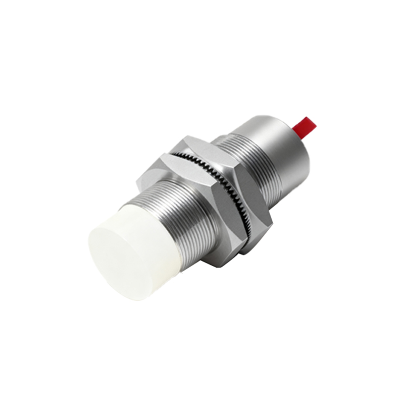
Next, focus on the wiring connections. Proximity sensors with fiber optics usually interface with amplifiers or controllers. The diagram will detail electrical terminals for power supply, output signals, and ground. Common terminals include V+ (positive voltage), V- (negative or ground), and OUT (output signal). For fiber optic models, the diagram may also show separate connections for the fiber optic cable to the amplifier unit. Pay attention to color-coding or numbering—for instance, brown wires for positive, blue for negative, and black for output. This standardization helps prevent wiring errors.
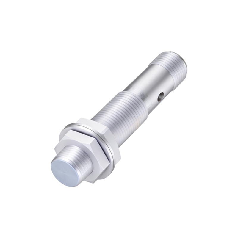
Another key aspect is understanding the output configuration. Proximity sensors can have NPN (sinking) or PNP (sourcing) outputs, which affect how they connect to PLCs or other devices. The wiring diagram will indicate this with symbols: an arrow pointing inward for NPN or outward for PNP. In fiber optic setups, the output type is often determined by the amplifier, so check the amplifier section of the diagram. Additionally, note any diagnostic indicators, like LED lights on the sensor or amplifier, which are shown as small circles with labels (e.g., "PWR" for power, "ALM" for alarm).
The fiber optic portion requires special attention. Diagrams illustrate the path from the sensor head to the amplifier, including connectors and splices. Look for symbols representing connectors (e.g., squares or triangles) and note their types, such as SMA or ST connectors, as mismatches can cause signal loss. The diagram may also specify fiber optic cable types, like single-mode or multi-mode, which impact sensing range and accuracy. Ensure the cable is correctly routed away from electrical noise sources, as indicated by separation lines or notes on the diagram.
Practical steps for reading include:
1. Start with the title block or legend to identify components and abbreviations.
2. Trace the power circuit from the supply to the sensor and amplifier, verifying voltage ratings (e.g., 12-24V DC).
3. Follow the fiber optic path to confirm proper alignment and connection points.
4. Check output wiring to the load device, ensuring compatibility with NPN/PNP logic.
5. Review any notes or warnings about installation, such as minimum bending radius for fiber cables or environmental limits.
Common pitfalls include misinterpreting symbols—for example, confusing a reflective sensor diagram (with light bouncing off a target) with a through-beam type (separate TX and RX). Always refer to the manufacturer's datasheet for specifics, as diagrams can vary by brand. In fiber optic systems, signal attenuation is a concern; the diagram might include notes on maximum cable length or loss thresholds.
In summary, reading proximity sensor fiber optic wiring diagrams involves a systematic approach: identify symbols, understand electrical and optical connections, and verify output configurations. With practice, you'll quickly diagnose issues like wiring faults or signal drops, enhancing system performance. Remember, these diagrams are your roadmap to efficient sensor deployment—take time to study them thoroughly before installation.