Proximity sensors are widely used in industrial automation for detecting the presence or absence of objects without physical contact. Proper wiring of their terminals is crucial for reliable operation and safety. This guide explains the fundamentals of proximity sensor terminal wiring, covering common types, wiring configurations, and best practices.
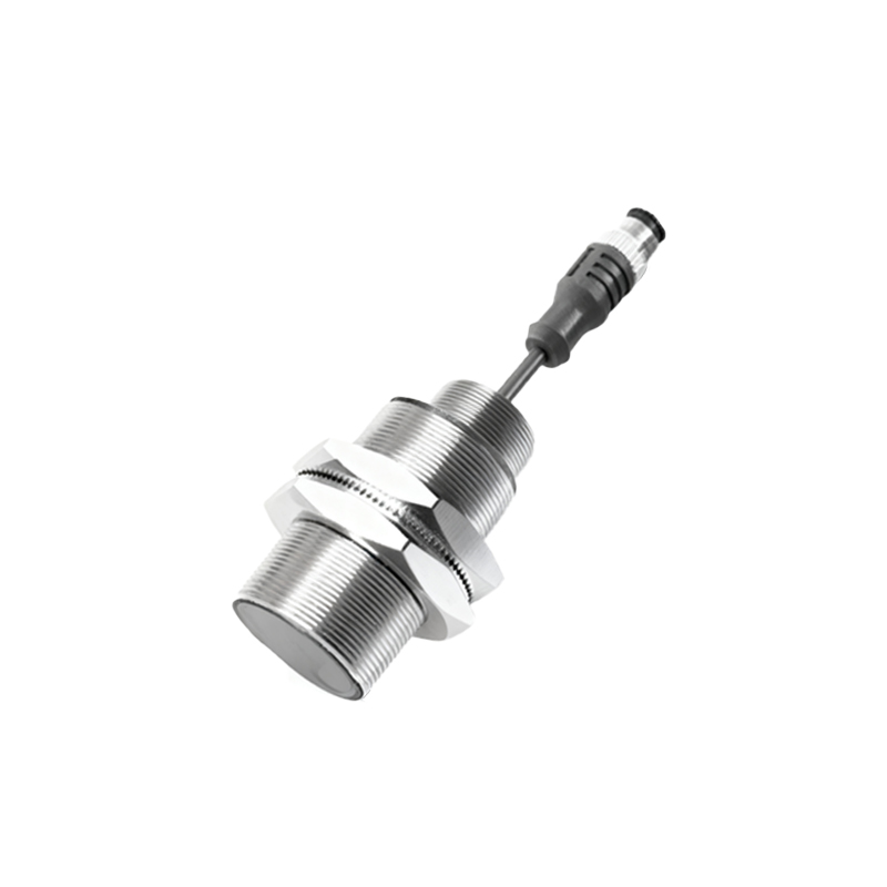
Proximity sensors typically have three or four terminals, depending on their design and functionality. The most common types include inductive sensors (for metal detection) and capacitive sensors (for non-metal materials). Each sensor has clearly labeled terminals, usually marked as:
- Brown wire (or L+): Connected to the positive DC supply voltage (e.g., 10-30 VDC).
- Blue wire (or L-): Connected to the negative DC supply or ground.
- Black wire (or OUT): The output signal wire, which switches based on object detection.
- White wire (or auxiliary output): Sometimes present for complementary signals or special functions.
Wiring configurations vary between NPN (sinking) and PNP (sourcing) outputs. NPN sensors switch the output to ground when activated, commonly used in Asia and Europe. PNP sensors switch the output to positive voltage, preferred in North America. Always check the sensor datasheet to match the correct type with your control system (e.g., PLC input modules). For example, wiring an NPN sensor to a PNP-compatible device may cause malfunction or damage.
Shielded cables are recommended for wiring to reduce electrical noise interference, especially in environments with motors or frequency drives. Connect the cable shield to ground at one end only, typically at the control panel, to avoid ground loops. Ensure terminals are tightened securely using appropriate tools, but avoid over-tightening to prevent damage. For long cable runs, consider voltage drop issues—using thicker gauge wires can help maintain signal integrity.
Safety precautions are essential. Always disconnect power before wiring to prevent electric shock or short circuits. Verify the sensor’s voltage rating and polarity; reverse polarity can permanently damage the device. Use conduit or cable ducts in harsh environments to protect wires from moisture, chemicals, or physical abrasion. After wiring, test the sensor with a target object to confirm output response, and use a multimeter if needed to check voltage levels.
In summary, correct proximity sensor terminal wiring ensures accuracy and longevity in automation systems. By understanding terminal labels, choosing the right output type, and following installation guidelines, users can optimize performance and minimize downtime. Regular maintenance, such as inspecting connections for corrosion or looseness, further enhances reliability.