Proximity sensors are critical components in industrial automation, particularly when integrated with servo motor systems. These sensors provide precise detection of object presence or position, enabling accurate control and feedback for servo-driven applications. Understanding the correct wiring methodology is essential for ensuring system reliability, safety, and optimal performance. This article outlines a comprehensive wiring diagram and step-by-step guidance for connecting proximity sensors to servo motors, adhering to industry standards and best practices.
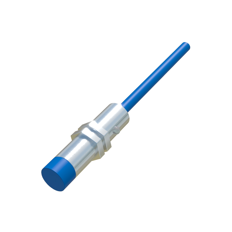
Proximity sensors commonly used with servo motors include inductive, capacitive, and magnetic types, each suited for specific environments and materials. Inductive sensors are ideal for detecting metallic objects, while capacitive sensors can handle non-metallic materials. Magnetic sensors, such as Hall-effect types, are often employed in rotary or linear position feedback within servo systems. Before wiring, verify the sensor specifications—including voltage rating (typically 12-24V DC or 110-240V AC), output type (PNP or NPN), and sensing range—to match the servo controller requirements.
A standard wiring setup involves connecting the proximity sensor to a servo motor driver or programmable logic controller (PLC). For a DC-powered sensor, follow these steps: First, identify the power supply terminals. Connect the positive wire (usually brown or red) from the sensor to the DC positive terminal of the power source, and the negative wire (blue or black) to the DC negative terminal. The output wire (often black or white) links to the input terminal of the servo controller. If using a PNP sensor (sourcing output), the output provides positive voltage when activated, requiring connection to a compatible high-input on the controller. For NPN sensors (sinking output), the output sinks to ground upon activation, necessitating a low-input connection. Always refer to the controller manual to confirm input compatibility.
Incorporate protective measures to prevent electrical issues. Use shielded cables to minimize electromagnetic interference from servo motors, which can generate noise during operation. Ground the shield at one end—preferably at the controller side—to avoid ground loops. Install fuses or circuit breakers in the power line to protect against overcurrent, and consider adding surge suppressors if the system operates in environments with voltage spikes. For AC-powered sensors, ensure proper isolation and use relays if interfacing with low-voltage servo controllers.
Testing and calibration are vital after wiring. Power on the system and observe the sensor indicator LED, which should illuminate when detecting a target. Use a multimeter to verify output voltage levels in active and inactive states. Program the servo controller to respond to sensor signals—for instance, triggering a stop or position change upon detection. Adjust the sensor’s sensitivity or alignment if false triggers occur, ensuring consistent operation within the servo’s dynamic range.
Common pitfalls include incorrect polarity, mismatched voltage levels, and inadequate shielding. Double-check wire connections against the diagram provided by manufacturers. For complex setups with multiple sensors, label wires clearly and maintain organized cable management to simplify troubleshooting. Regular maintenance, such as cleaning sensor faces and inspecting connections, prolongs system lifespan.
Integrating proximity sensors with servo motors enhances automation precision in applications like packaging, robotics, and CNC machinery. By following a detailed wiring diagram and adhering to safety protocols, engineers can achieve seamless communication between sensors and servo systems, reducing downtime and improving efficiency. Always consult technical datasheets and industry guidelines, such as IEC 60947-5-2, for compliance and performance assurance.