Proximity sensors are fascinating electronic devices that detect the presence or absence of an object within a specific range without physical contact. They are ubiquitous in modern technology, found in smartphones, automatic doors, industrial assembly lines, and robotics. For hobbyists, students, and DIY electronics enthusiasts, building a basic proximity sensor is an excellent project to understand fundamental principles of sensing, signal processing, and circuit design. This guide will walk you through creating a simple infrared (IR) proximity sensor, a common and accessible type.
The core principle of an IR proximity sensor involves emitting an infrared light beam and measuring the reflection. An object within range will reflect some of this light back to a receiver. The sensor interprets the intensity of the reflected light to determine proximity. The main components you will need are an IR LED (Light Emitting Diode) to emit the light, a photodiode or phototransistor to act as the receiver, resistors, a breadboard, jumper wires, and a power source like a 5V battery pack. An operational amplifier (op-amp) chip, such as the common LM358, is highly recommended to amplify the weak signal from the receiver for reliable detection.
Start by placing the IR LED and the photodiode on the breadboard. Position them side-by-side but ensure they are not directly facing each other to prevent the receiver from detecting the emitter's light without reflection. Connect the anode (longer lead) of the IR LED to a current-limiting resistor (typically 100-330 ohms) and then to the positive power rail. The cathode connects to ground. This circuit allows the LED to emit a constant beam of infrared light, invisible to the human eye.
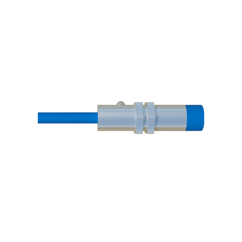
Next, build the receiver circuit. Connect the photodiode's cathode to the positive rail and its anode to a pull-up resistor (e.g., 10k ohms) that goes to ground. The voltage at the junction between the photodiode and the resistor will change based on the amount of infrared light hitting the photodiode. More reflected light causes more current to flow through the photodiode, altering this voltage. This signal point is where you connect the input of your op-amp circuit.
The raw signal from the photodiode is very subtle. To make it usable, configure the op-amp as a comparator. Using the LM358, connect the photodiode's signal point to the non-inverting input (pin 3). Create a reference voltage using a voltage divider (two resistors) and connect it to the inverting input (pin 2). The op-amp will compare these two voltages. When the reflected light is strong enough (object is close), the signal voltage exceeds the reference, causing the op-amp's output (pin 1) to swing high (close to 5V). When no object is present, the output remains low (0V). You can connect this output to an LED with a resistor to provide a visual indicator of detection.
Once the circuit is assembled, the crucial phase is calibration and testing. Power the circuit and point the sensor at an empty space. Adjust the potentiometer in your voltage divider to set the reference voltage so that the output LED is off. Then, slowly bring an object, like your hand, towards the sensor. The detection LED should light up at a certain distance. Fine-tune the reference voltage and the physical angle between the IR LED and photodiode to achieve your desired sensing range, which for this simple setup might be between 2 to 10 centimeters. Shielding the components from ambient light with a small tube or housing can significantly improve reliability.
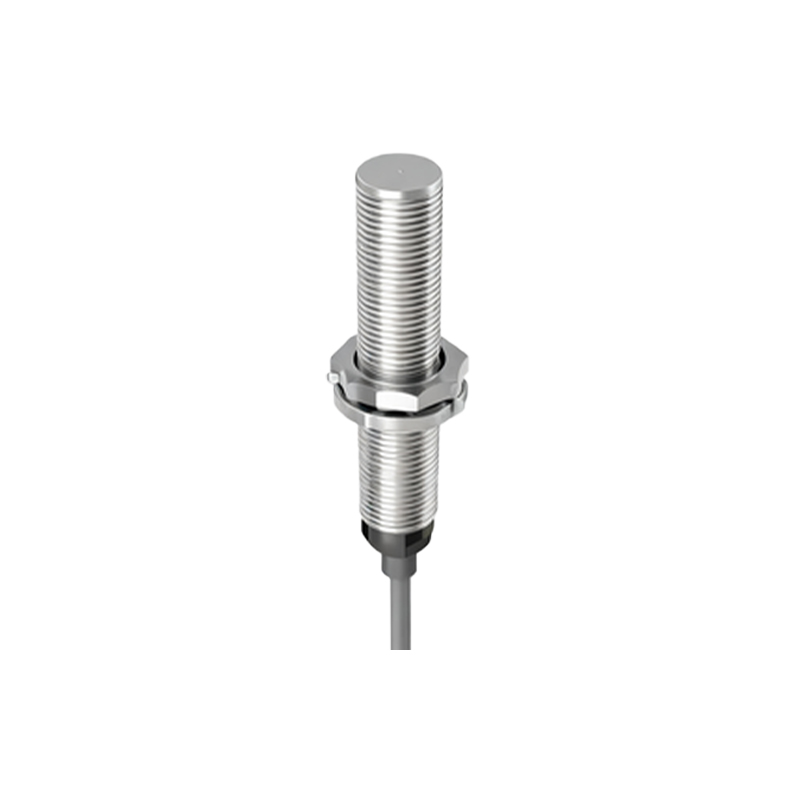
This basic IR sensor has limitations. It can be affected by bright ambient light and the color/reflectivity of the target object. For more advanced applications, consider using a modulated IR signal. This technique involves rapidly turning the IR LED on and off at a specific frequency (e.g., 38 kHz). The receiver circuit is then tuned to only amplify signals at that same frequency, effectively filtering out interference from other light sources. This requires an oscillator circuit for the LED and a dedicated IR receiver module.
Building a proximity sensor from scratch provides invaluable hands-on experience. It demystifies the technology inside everyday gadgets and lays the groundwork for more complex projects like obstacle-avoiding robots, touchless switches, or automated systems. Remember to always double-check your circuit connections before applying power. With patience and careful calibration, you will have a functional sensor that brings your interactive electronic projects one step closer to reality.