For electrical engineers and maintenance technicians working in industrial automation, proximity sensors are ubiquitous. These non-contact devices reliably detect the presence or absence of metallic or non-metallic objects, forming the backbone of countless control systems for positioning, counting, and safety. However, when a sensor on the production line malfunctions, downtime costs escalate rapidly. While commercial diagnostic tools are available, a custom-built proximity sensor tester offers unparalleled flexibility, cost-effectiveness, and a deeper understanding of sensor operation. This guide details the construction and application of a versatile, handheld DIY tester designed for inductive, capacitive, and sometimes photoelectric sensors.
The core philosophy behind this instrument is simulation and measurement. A functional tester must be able to mimic a target object for the sensor and simultaneously monitor the sensor's output signal. Our design centers on a compact, battery-powered unit housed in a durable plastic enclosure. The primary components include a microcontroller (like an Arduino Nano or ATtiny), a dual-color LED for status indication, a buzzer for audible feedback, a high-brightness LED to simulate a reflective target for photoelectric sensors, and a small piece of mild steel (for inductive targets) mounted on the case. The heart of the circuit is the input stage, which must safely interface with a wide range of sensor voltages (commonly 10-30V DC).
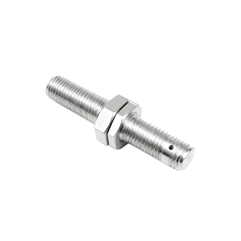
For testing standard 3-wire DC sensors (PNP or NPN), the input circuit utilizes optocouplers. This provides essential galvanic isolation, protecting the microcontroller from potential voltage spikes or incorrect wiring by the user. Two optocouplers are configured to detect both sourcing (PNP) and sinking (NPN) signals. The microcontroller, programmed via the Arduino IDE, reads the state of these optocouplers. The logic is straightforward: when the sensor activates (detects the simulated target), its output switches. The optocoupler detects this change, and the microcontroller lights the green LED and sounds a short beep. If no signal is present when expected, the red LED remains lit. This provides immediate go/no-go diagnostics.
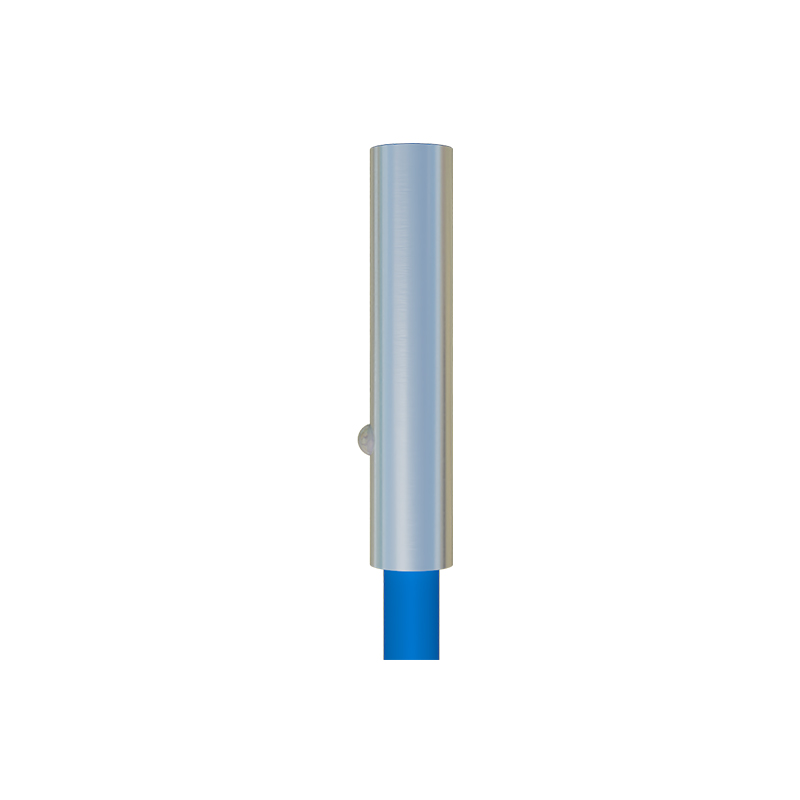
The testing procedure is intuitive. To evaluate an inductive proximity sensor, simply bring the steel target area on the tester's case close to the active face of the sensor. The tester, connected to the sensor's output wire and power supply common, will immediately indicate detection. For capacitive sensors, which react to the proximity of any material, the user's hand or the enclosure itself can serve as the target. The integrated high-power LED acts as a simulated light source for testing diffuse-reflective photoelectric sensors. By pointing the tester's LED towards the sensor and receiving the reflected light, one can verify the sensor's functionality. The buzzer's pulse rate can even be programmed to vary with signal strength, offering a crude analog assessment.
Beyond basic functionality testing, enhancements can transform this tool into a diagnostic powerhouse. Adding a small OLED display allows for visualizing switching frequency, which is critical for high-speed counting applications. Incorporating a simple potentiometer circuit lets the tester output a variable analog voltage (0-10V) or a PWM signal, enabling the calibration and testing of analog-output proximity sensors. Another advanced feature is a programmable pulse generator, which can send a simulated encoder signal to test the response of high-speed counters connected to sensor arrays. For field technicians, integrating a small, rechargeable lithium battery with a USB-C charging port ensures all-day usability.
Building this instrument is more than an exercise in soldering; it's a profound learning experience. It forces the engineer to consider sensor specifications—switching current, leakage current, voltage drops, and output types—in a practical context. Troubleshooting a sensor system becomes methodical: first, verify power supply with a multimeter; second, use the DIY tester to isolate whether the fault lies in the sensor's detection ability or its output switching circuitry; third, use the tester's signal simulation mode to check the downstream PLC input or controller. This systematic approach minimizes guesswork and restores operations faster.
In conclusion, this DIY proximity sensor debugging instrument is a testament to practical engineering. It empowers professionals to move beyond reliance on pre-packaged solutions, fostering a deeper diagnostic intuition and providing a customizable tool tailored to specific plant floor challenges. The construction cost is a fraction of a commercial unit, but the value gained in knowledge, troubleshooting speed, and operational continuity is immense. In the dynamic environment of industrial electrical maintenance, such a tool is not just convenient; it is an essential component of a proficient engineer's toolkit.