In industrial automation and control systems, proximity sensors play a critical role in detecting the presence or absence of objects without physical contact. The reliability and accuracy of these sensors heavily depend on a stable and well-designed power supply circuit. This article delves into the essential components, design considerations, and practical implementation of power supply circuits tailored for inductive, capacitive, and photoelectric proximity sensors.
A typical proximity sensor power supply circuit begins with a primary power source, often 24V DC in industrial settings, though 12V DC or AC variants are also common. The circuit must incorporate protection mechanisms against voltage spikes, reverse polarity, and electromagnetic interference (EMI). Key components include a voltage regulator, such as a linear regulator or switching regulator, to maintain a constant output voltage. For instance, a 7805 linear regulator can provide a steady 5V output from a higher input voltage, suitable for sensor logic circuits. Additionally, transient voltage suppressors (TVS diodes) and ferrite beads are employed to filter out noise and protect sensitive sensor electronics.
Designing the circuit requires careful attention to current consumption and voltage drop. Proximity sensors, especially inductive types, may draw significant inrush currents during activation. Therefore, the power supply must handle peak currents without voltage sag. Capacitors, both electrolytic and ceramic, are placed near the sensor and regulator to smooth voltage fluctuations and provide instantaneous current. A common configuration involves a 100µF electrolytic capacitor at the input and a 10µF tantalum capacitor at the output, coupled with a 0.1µF ceramic capacitor for high-frequency decoupling.
For sensors operating in harsh environments, isolation and grounding are paramount. An isolated DC-DC converter can prevent ground loops and enhance safety by separating the sensor circuit from the main power supply. This is crucial in applications involving flammable materials or high-voltage equipment. Furthermore, incorporating a current-limiting resistor or a fuse protects against short circuits, ensuring long-term durability.
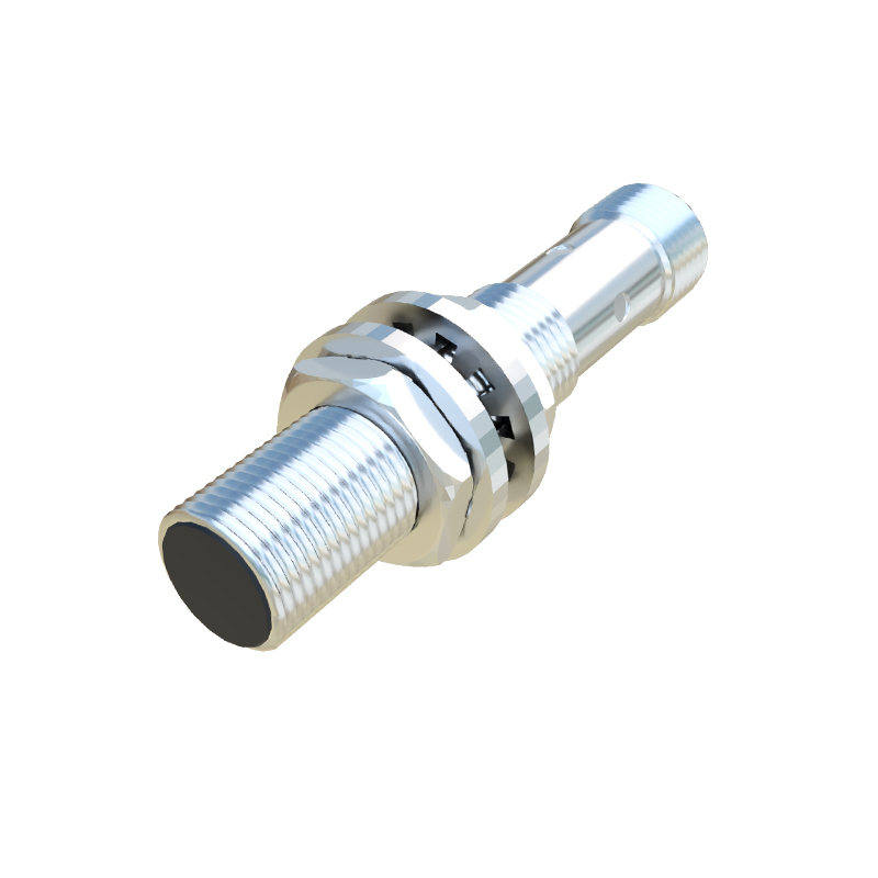
In practice, the circuit layout on a printed circuit board (PCB) must minimize noise and heat generation. Traces should be kept short and wide for power lines to reduce resistance and inductance. Placing components close to the sensor connector reduces parasitic effects. Thermal management, through heat sinks or thermal vias, is necessary for regulators dissipating excess power.
Testing and validation are final steps to ensure circuit performance. Using an oscilloscope, engineers can monitor output voltage stability under load variations and check for ripple or noise. Environmental tests, including temperature cycling and vibration, verify robustness in real-world conditions.
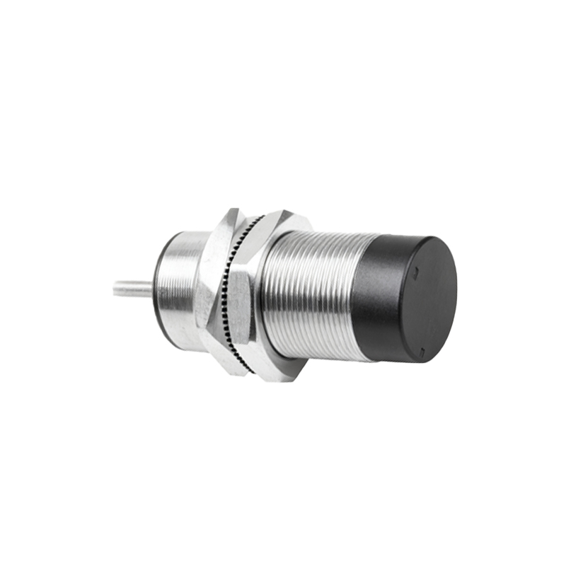
By adhering to these design principles, engineers can develop reliable power supply circuits that enhance the performance and lifespan of proximity sensors, contributing to efficient and safe automation systems.