Proximity sensors are indispensable components in modern industrial automation, offering non-contact detection of metallic or non-metallic objects. Proper calibration and debugging are critical to ensure reliable operation, minimize false triggers, and extend sensor lifespan. This guide provides a systematic approach for engineers to configure and troubleshoot common inductive, capacitive, and ultrasonic proximity sensors.
Understanding Sensor Fundamentals
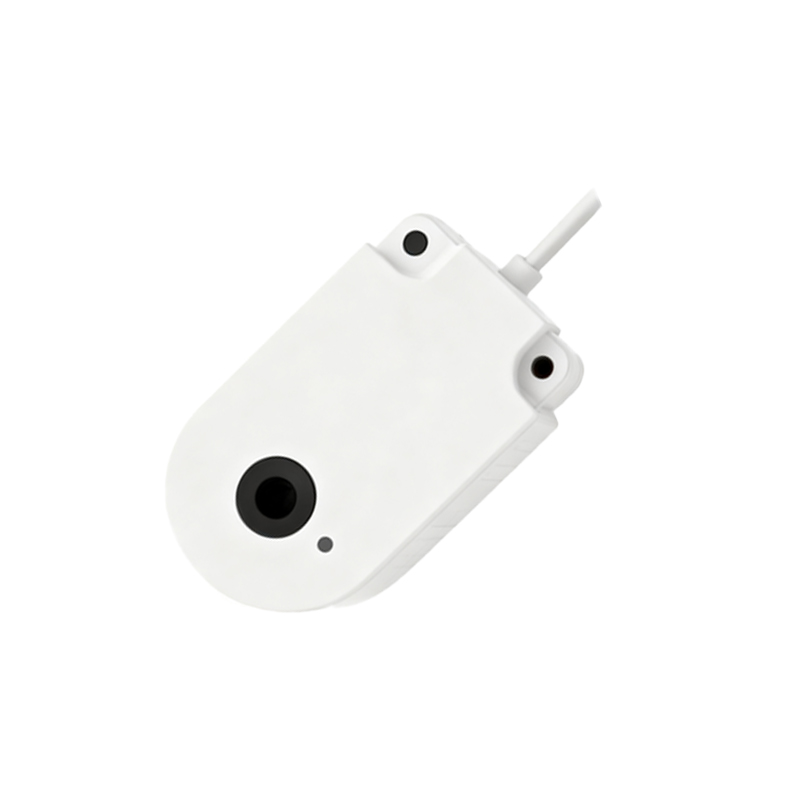
Before beginning any calibration, verify the sensor type and its specifications. Inductive sensors detect metals, capacitive sensors detect both metals and non-metals (like liquids or plastics), and ultrasonic sensors use sound waves for distance measurement. Always consult the manufacturer's datasheet for the sensing range, supply voltage, output type (PNP/NPN, NO/NC), and environmental ratings (IP, temperature). Ensure the power supply is stable and matches the sensor's requirements, typically 10-30V DC for most industrial models.
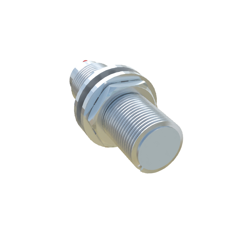
Initial Installation and Wiring Check
Mount the sensor securely, ensuring no excessive vibration. Maintain the recommended clearance around the sensing face—usually 1-2 times the sensor diameter—to prevent interference from the mounting bracket or nearby metal. For cylindrical sensors, a standard rule is to keep a non-metallic clearance of at least one sensor diameter radially. Check wiring meticulously: brown wire to DC+, blue wire to DC-, and the black (or white) wire as the output signal. For a 3-wire sensor, a wiring error is a common cause of failure. Use a multimeter to confirm voltage at the sensor terminals.
Step-by-Step Calibration Procedure
1. Power On and Preliminary Test: Apply power. Many sensors have an LED indicator. A steady or blinking LED often signifies power and standby mode. Refer to the manual for specific LED codes.
2. Set the Sensing Distance: Place the target material (the exact material to be detected in the application) at the desired nominal sensing distance. For adjustable sensors, use a non-metallic tool to turn the potentiometer. Slowly adjust until the output LED activates (or deactivates, depending on logic). For sensors with teach-in functionality, press the button while presenting the target at the required distance.
3. Hysteresis Setting: Hysteresis is the difference between the switch-on and switch-off points, preventing chatter. After setting the operating point, move the target away until the output drops. The distance between this drop-out point and the original operating point is the hysteresis. Some advanced sensors allow adjustment of this value. For stable operation, ensure the hysteresis is sufficient for your application's speed and mechanical tolerance.
4. Response Time Adjustment: If the sensor has a response time setting (often for filtering noise), set it according to the required detection speed. A faster response time is needed for high-speed lines but may be more susceptible to electrical noise. A slower setting can filter out noise but might miss fast-moving objects.
5. Final Validation: Move the target in and out of the sensing field repeatedly at the operational speed. Monitor the output with an oscilloscope or a PLC input indicator to ensure clean, consistent switching without false pulses.
Common Debugging and Troubleshooting Techniques
No Output Signal: Confirm power and wiring. Check if the load (e.g., PLC input, relay) is within the sensor's current rating. Test by temporarily connecting a known-good indicator LED with a series resistor.
Inconsistent or Reduced Sensing Range: This often indicates external interference. Check for nearby sensors operating at similar frequencies, large motors, variable frequency drives (VFDs), or welding equipment. Increase separation distance, use shielded cables, and ensure proper grounding of the sensor body and shield. For capacitive sensors, changes in ambient humidity or material composition can affect performance; readjust the sensitivity.
Sensor Triggers Without a Target: Electrical noise is the most likely culprit. Implement noise suppression: use ferrite cores on cables, install surge protectors, and ensure the grounding system is low-impedance. For DC sensors, keep signal cables away from AC power lines. For inductive sensors, check for accumulation of metallic dust on the sensing face.
Shortened Sensor Life: Typically caused by electrical overload or harsh physical environments. Verify that inrush currents from solenoids or contactors are not damaging the output transistor. Use protective circuits if necessary. Ensure the sensor is not exposed to chemicals beyond its specification or subjected to direct physical impact.
Advanced Tips for Optimal Performance
- For detecting small objects, use a sensor with a higher frequency response.
- When detecting different materials, capacitive sensors may need re-calibration for each material type.
- In high-vibration environments, consider sensors with built-in vibration resistance and use locking nuts on mounting threads.
- Regularly perform preventive maintenance checks, cleaning the sensing face and verifying the