In industrial automation and electronic control systems, proximity sensors are indispensable components for detecting the presence or absence of objects without physical contact. A common yet perplexing issue faced by engineers is the failure of the sensor's status to display on the designated Human-Machine Interface (HMI), Programmable Logic Controller (PLC) panel, or monitoring software. This "no display" scenario can halt production lines, cause diagnostic delays, and lead to significant downtime. This article delves into the root causes, systematic troubleshooting methodologies, and effective solutions for proximity sensor display failures, tailored for electrical engineering professionals.
The absence of a display indication, while the sensor might be physically operational, typically points to a breakdown in the signal chain between the sensor and the display unit. The first and most critical step is to distinguish between a complete sensor failure and a display/communication failure. Begin by verifying the sensor's basic operation independently. Use a multimeter to check the output signal at the sensor's terminals when a target is presented and removed. For a standard 3-wire DC sensor, you should observe a clear voltage shift (e.g., from 24V to 0V for an NPN sinking sensor, or 0V to 24V for a PNP sourcing sensor) on the signal wire. If the sensor provides a correct electrical output, the problem lies downstream.
A primary culprit is wiring and connection integrity. Inspect the entire cable run from the sensor to the input module or display device. Look for physical damage, loose terminals in junction boxes or ducting, corrosion, and pinched wires. Pay special attention to shield connections if a shielded cable is used; a poorly grounded shield can introduce noise that disrupts signal interpretation. Ensure the correct wiring scheme: the brown wire (typically +V) to positive supply, blue wire to common negative (0V), and the black (or white) signal wire to the controller's input channel. A swapped wire between power and signal will prevent proper operation.
Power supply issues are equally prevalent. Measure the voltage at the sensor itself under load, not just at the power source. A voltage drop below the sensor's operational threshold (e.g., less than 18V for a nominal 24V DC sensor) due to long cable runs, undersized wires, or a failing power supply can cause erratic behavior. Also, check for electrical noise or voltage spikes on the supply line from nearby high-power equipment like motor drives or welders. These can interfere with the sensor's internal circuitry or corrupt the signal read by the PLC. Implementing a dedicated, regulated power supply for sensors or using noise filters can be an effective countermeasure.
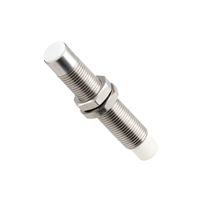
The configuration of the input channel on the PLC or receiving device is a frequent oversight. The input module must be correctly configured to match the sensor type (PNP vs. NPN, also known as sourcing vs. sinking). Connecting a PNP sensor to an input card configured or wired for NPN signals will result in no valid signal detection. Furthermore, verify the input addressing in the PLC program. A simple programming error, such as pointing to an incorrect input address (I0.1 instead of I0.0), will show no status change on the HMI. Check the diagnostic LEDs on the PLC input module; a lit LED usually indicates a valid signal is being received, which would then point to a software or HMI configuration issue.
The display system itself requires investigation. On the HMI or SCADA software, confirm that the tag linking the PLC input address to the graphical indicator (e.g., a lamp icon) is correctly configured and that the animation properties are set properly. The display object might be hidden behind another graphic element or placed on a non-visible screen. Communication faults between the PLC and the HMI, such as a broken network cable, incorrect baud rate settings, or IP address conflicts, will prevent any data, including sensor status, from being displayed. Review the communication driver settings and network diagnostics.
Environmental factors should not be underestimated. Proximity sensors, especially inductive types, have a specified sensing distance. Accumulation of metallic dust, paint, or other contaminants on the sensor face can drastically reduce its effective range, causing intermittent detection. Excessive ambient temperature beyond the sensor's rating can lead to internal circuit failure. For capacitive or optical sensors, changes in the target material, moisture, or oil mist can affect performance. Always ensure the sensor is selected appropriately for the specific environmental conditions of the application.
In summary, a structured approach is key. Start at the sensor: verify its raw output. Then move along the signal path: check power, wiring, and connections. Proceed to the controller: validate input module configuration and hardware addressing. Finally, examine the software layer: PLC logic, HMI tags, and communication links. By methodically isolating each segment of the system, electrical engineers